
Degradation fault point identification method, device and system

An identification method and identification device technology, applied in transmission systems, digital transmission systems, electrical components, etc., can solve the problems of inconvenient positioning and large-scale network operation and maintenance management

Active Publication Date: 2020-01-31
CHINA UNITED NETWORK COMM GRP CO LTD
View PDF11 Cites 6 Cited by
  • Summary
  • Abstract
  • Description
  • Claims
  • Application Information

AI Technical Summary

Problems solved by technology

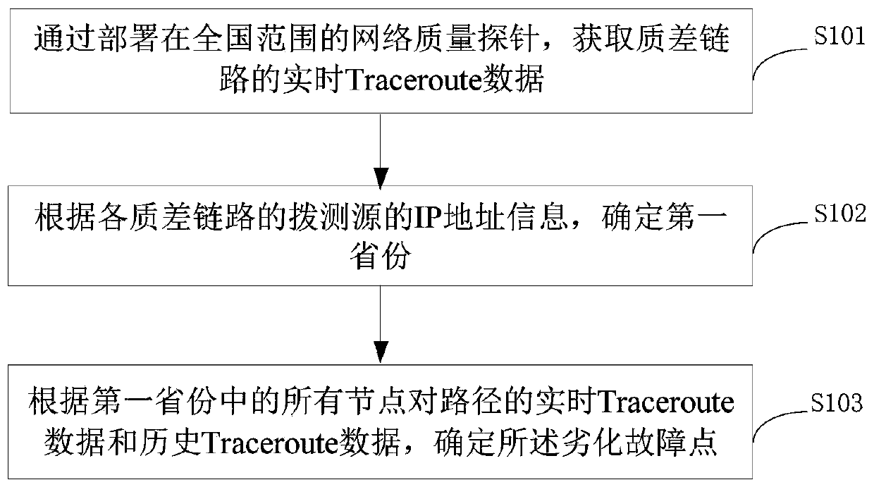
[0005] The present application provides a method, device and system for identifying degraded fault points, which are used to solve the problem of inconvenient operation and maintenance management of large-scale networks caused by the difficulty in locating fault points that cause network delays in the prior art

Method used


Image

  • Degradation fault point identification method, device and system
  • Degradation fault point identification method, device and system
  • Degradation fault point identification method, device and system

Examples


Embodiment Construction

[0083] Reference will now be made in detail to the exemplary embodiments, examples of which are illustrated in the accompanying drawings. When the following description refers to the accompanying drawings, the same numerals in different drawings refer to the same or similar elements unless otherwise indicated. The implementations described in the following exemplary examples do not represent all implementations consistent with the present disclosure. Rather, they are merely examples of apparatuses and methods consistent with aspects of the present disclosure as recited in the appended claims.

[0084] In the prior art, the network delay is measured by Ping. Although the quality of the network plays an evaluation role, this is only a rough measurement method. On the one hand, the existing measurement method cannot perceive the impact of each node on the path. On the other hand, there is no fixed reference standard in the existing measurement methods to judge whether the networ...


PUM


Abstract

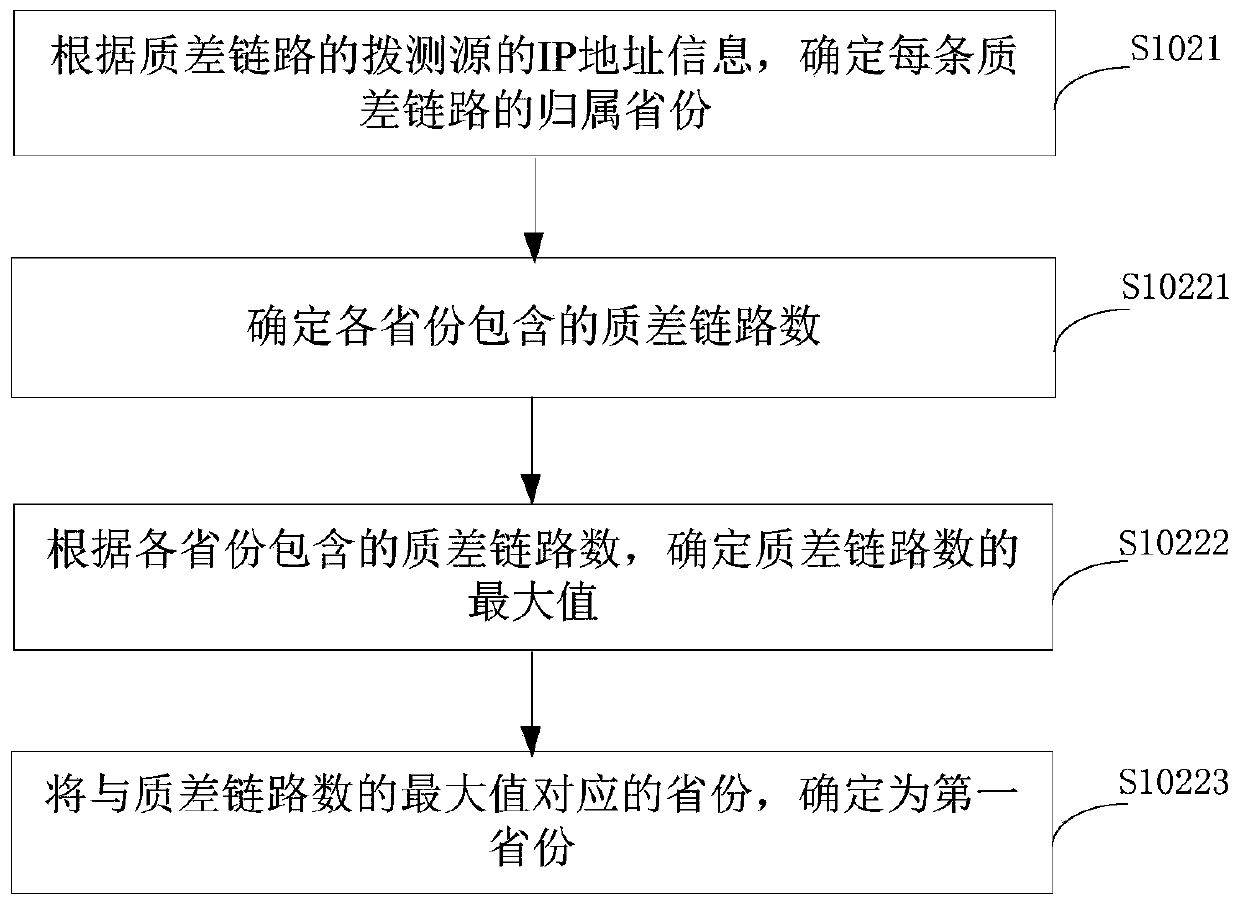
The invention provides a degradation fault point identification method, device and system. The identification method comprises the following steps: deploying nationwide network quality probes, acquiring real-time Trace data of a poor-quality link; according to the IP address information of the dial testing source of each poor-quality link, obtaining IP address information; determining a first province, determining the degradation fault point according to the real-time Trace data and historical Trace data of all nodes to the path in the first province. Accurate identification of network degradation and accurate positioning of the degradation occurrence position are realized, and thus operation and maintenance management of a large-scale network is facilitated.

Description

technical field [0001] The present application relates to the technical field of network detection, and in particular to a method, device and system for identifying a degradation fault point. Background technique [0002] With the continuous development of communication technology and the continuous expansion of network capacity, various communication services have higher and higher requirements for network communication quality. Therefore, grasping the communication quality of the network in time and locating the fault points that cause poor network quality are of great significance for network operators to manage the network, repair faults and expand services. [0003] It is a relatively common method to measure the communication quality of a network through network delay. Network delay refers to the time required for a message or packet to be transmitted from one end of a network to the other end. In the prior art, network administrators usually use Ping to measure netwo...

Claims


Application Information

Patent Timeline
Patent Type & Authority Applications(China)
IPC IPC(8): H04L12/24
CPCH04L41/0677H04L41/0631H04L41/50
Inventor 徐舒龙柯陈孟尝莫俊彬潘俊斌吴浩杨世标彭锐田旺旺武春花雷迎颖梁洪智
Owner CHINA UNITED NETWORK COMM GRP CO LTD
Learn More