Eureka AIR delivers breakthrough ideas for toughest innovation challenges, trusted by R&D personnel around the world.

Method for determining the overall utility vehicle deceleration values which can be achieved by actuating wheel brakes, brake system for carrying out the method, and utility vehicle comprising same

A technology for wheel brakes and braking equipment, which is applied in the field of commercial vehicles or vehicle combinations, and can solve the problem of not running out of reliable information.

Active Publication Date: 2020-01-31
WABCO GMBH
View PDF9 Cites 0 Cited by
  • Summary
  • Abstract
  • Description
  • Claims
  • Application Information

AI Technical Summary

Problems solved by technology

The fuel consumption reduction potential of vehicle platooning may not be exhausted with reliable information on the achievable total braking force

Method used


Image

  • Method for determining the overall utility vehicle deceleration values which can be achieved by actuating wheel brakes, brake system for carrying out the method, and utility vehicle comprising same
  • Method for determining the overall utility vehicle deceleration values which can be achieved by actuating wheel brakes, brake system for carrying out the method, and utility vehicle comprising same
  • Method for determining the overall utility vehicle deceleration values which can be achieved by actuating wheel brakes, brake system for carrying out the method, and utility vehicle comprising same

Examples


Embodiment Construction

[0026] specific implementation plan

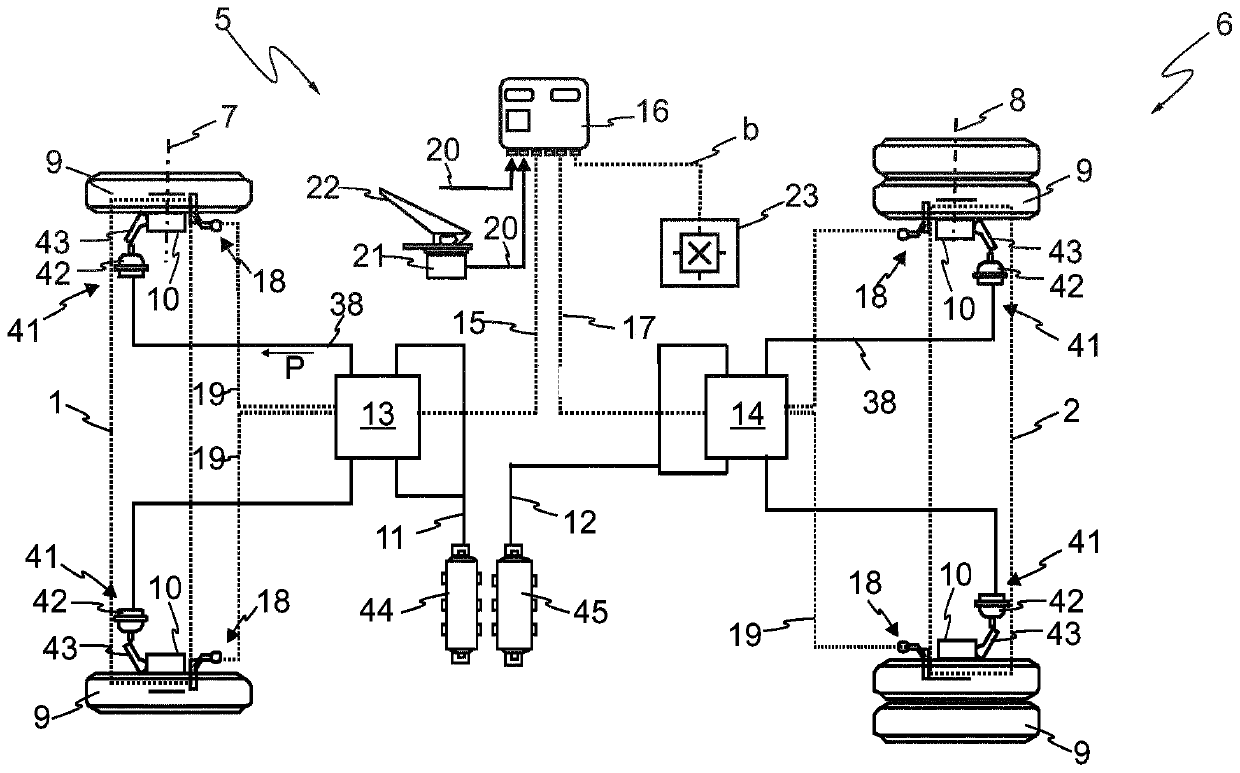
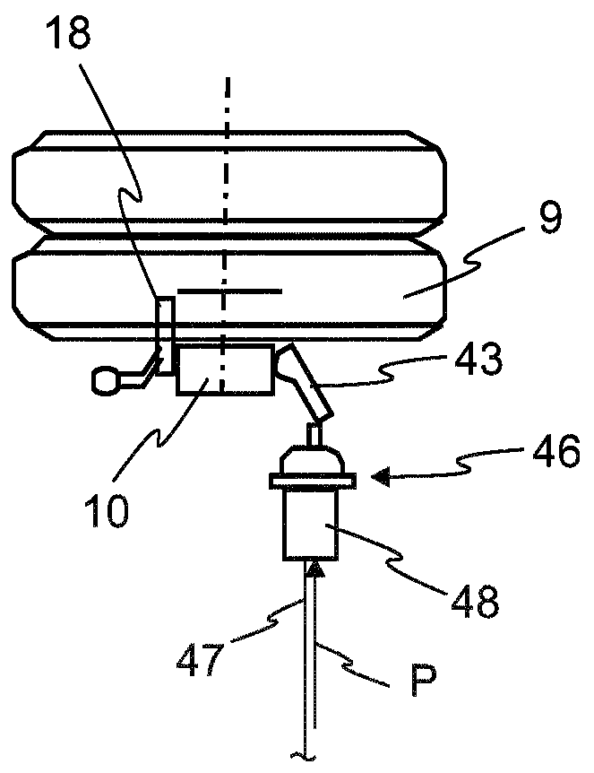
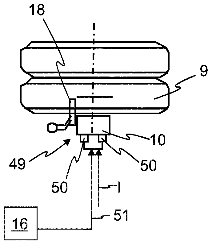
[0027] figure 1 An electro-pneumatic schematic diagram of an electronic brake system 5 of a commercial vehicle 6 is shown. Electrical circuits are shown in dashed lines and pneumatic circuits are shown in solid lines. In the exemplary embodiment shown, the commercial vehicle 6 comprises two axles 7 , 8 on which wheels 9 are arranged on each side. To decelerate (brake) the commercial vehicle 6 , a wheel brake 10 is assigned to each wheel 9 . in accordance with figure 1 In the exemplary embodiment, the brake system 5 has a pneumatic operating system 41 so that the wheel brakes 10 can be operated pneumatically and apply the braking force to the rotating wheel 9 corresponding to the required braking pressure. The pneumatic operating system 41 consists of a pneumatic brake cylinder 42 connected to the wheel brake 10 as well as a brake lever 43 and a pressure piston which is arranged within the wheel brake 10 . Brake cylinder 42 generates an ...


PUM


Abstract

The invention relates to a method for determining the overall deceleration values (bmax, bmin), which can be achieved by actuating wheel brakes, of a utility vehicle (6) or a vehicle combination (24)comprising multiple axles (7, 8). The invention further relates to a brake system for carrying out the method and to a utility vehicle or a vehicle combination comprising such a brake system for carrying out the method. The aim of the invention is to determine the currently achievable overall deceleration values (bmax, bmin) for decelerating a utility vehicle or a vehicle combination with multipleaxles during travel. According to the invention, this is achieved in that the brake force is distributed (26) such that brake forces (F1, F2, F3, F4) are distributed unequally to brake units (1, 2, 3, 4) comprising the wheel brakes (10) of one or more axles (7, 8) in order to implement a deceleration request (20) during a partial braking process (27). One of the brake units (1, 2, 3, 4) is selected, and a greater brake force (F2) is applied by said selected brake unit (29) than via the other brake units (1, 3, 4), and a current deceleration b of the utility vehicle (6) or the vehicle combination (24) is measured or ascertained and paired with the respective selected brake unit (29) as the corresponding partial deceleration value (b1, b2, b3, b4) and is stored. The achievable overall deceleration values (bmin, bmax) are determined as the sum (31) of the partial deceleration values (b1, b2, b3, b4) of the brake units (1, 2, 3, 4).

Description

technical field [0001] The invention relates to a method according to claim 1 for determining the total deceleration value achievable by actuating the wheel brakes of a commercial vehicle or a combination of vehicles having a plurality of axles. The invention also relates to a braking system according to claim 8 for carrying out the method, and to a commercial vehicle or a combination of vehicles according to claim 9 having such a braking system. Background technique [0002] Automated braking systems such as the Advanced Emergency Braking System (AEBS = "advance emergency braking system (Advance Emergency Braking System)"), driver assistance systems such as Electronic Stability Control (ESC) are increasingly being used in modern commercial vehicles, where , the brake system automatically decelerates the vehicle as required via the electronic brake control unit independently of the driver's braking. Here, it is of particular interest to know as precisely as possible the tot...

Claims


Application Information

Patent Timeline
IPC IPC(8): B60T8/17B60T8/1766
CPCB60T8/1708B60T8/1766B60T8/1887B60T7/12B60T8/172B60T8/321B60T8/323B60T2201/022B60T2240/02B60T2250/00B60T2270/10
Inventor 托马斯·迪克曼斯特凡·卡伦巴赫托尔斯滕·瓦尔鲍姆克里斯蒂安·维恩
Owner WABCO GMBH
Why Eureka
Eureka Blog
Learn More