Electrical-device connecting apparatus and opening/closing apparatus
A technology for electrical equipment and connection devices, which is applied in the field of electrical equipment connection devices and switching devices, can solve problems such as difficult to ensure the insertion and extraction of exhaust tools, and the difficulty of exhaust operation itself, so as to achieve simple exhaust, The effect of efficient exhaust
- Summary
- Abstract
- Description
- Claims
- Application Information
AI Technical Summary
Problems solved by technology
Method used
Image


Examples
Embodiment approach 1
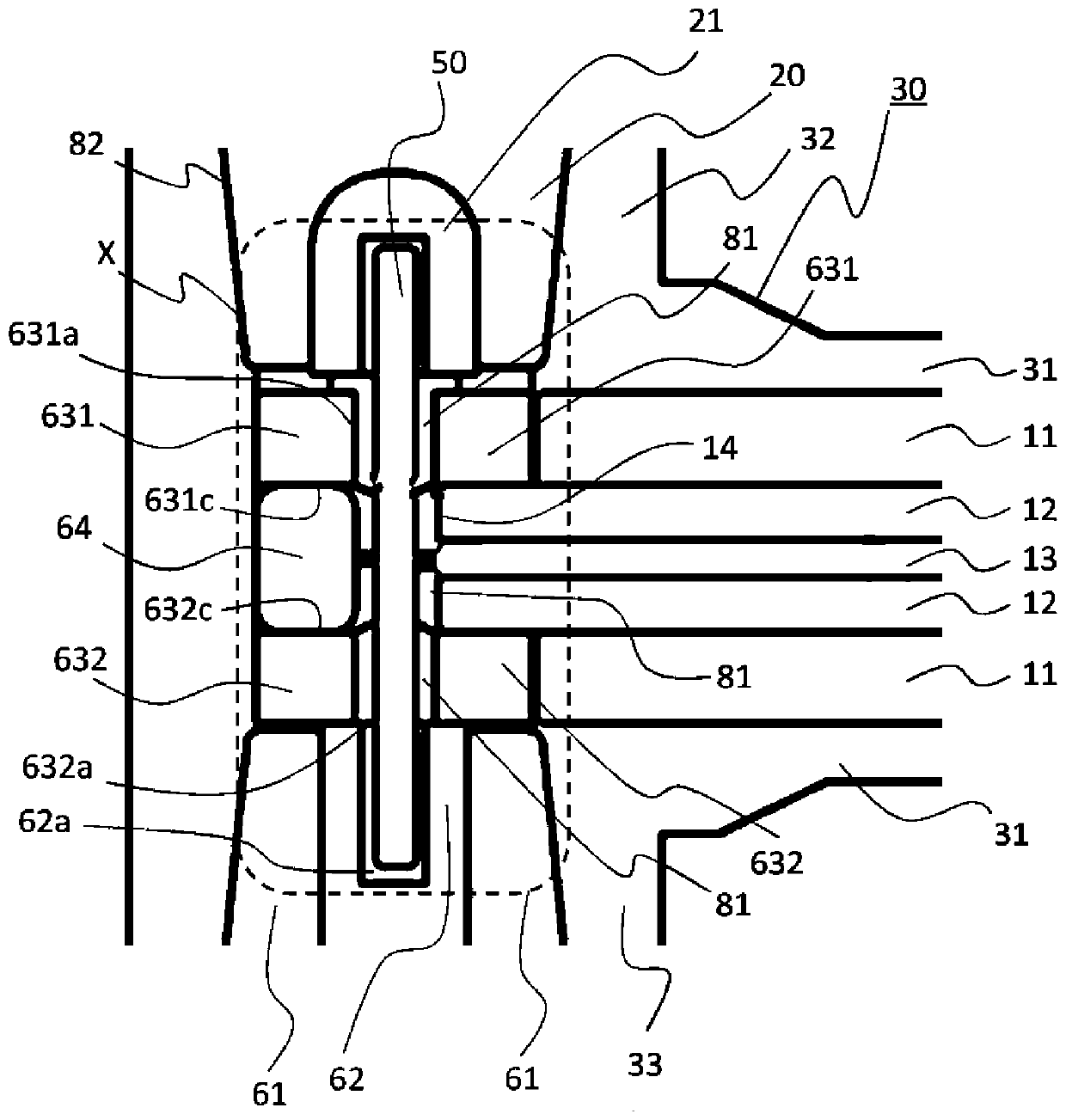
[0024] Below, based on Figure 1 to Figure 6 Embodiment 1 of the present invention will be described. figure 1 is a cross-sectional view showing the electrical equipment connection device according to Embodiment 1 of the present invention, figure 2 yes means figure 1 An enlarged cross-sectional view of part A. The electrical device connection device 100 includes: a bus bar 10, that is, a bus conductor, which extends along the direction in which a plurality of switch devices 91 respectively accommodate circuit breakers (not shown) The closing device 91 is electrically connected to each other; and the insulating plug 20, that is, the insulating cylinder, the above-mentioned insulating plug 20 will be connected to the instrument transformer 92 of the bus bar 10 on the opposite side to the switching device 91, that is, between the electrical equipment and the bus bar 10 Electrically insulated between them, terminal members 30, 40 are provided at positions corresponding to the ...
Embodiment approach 2
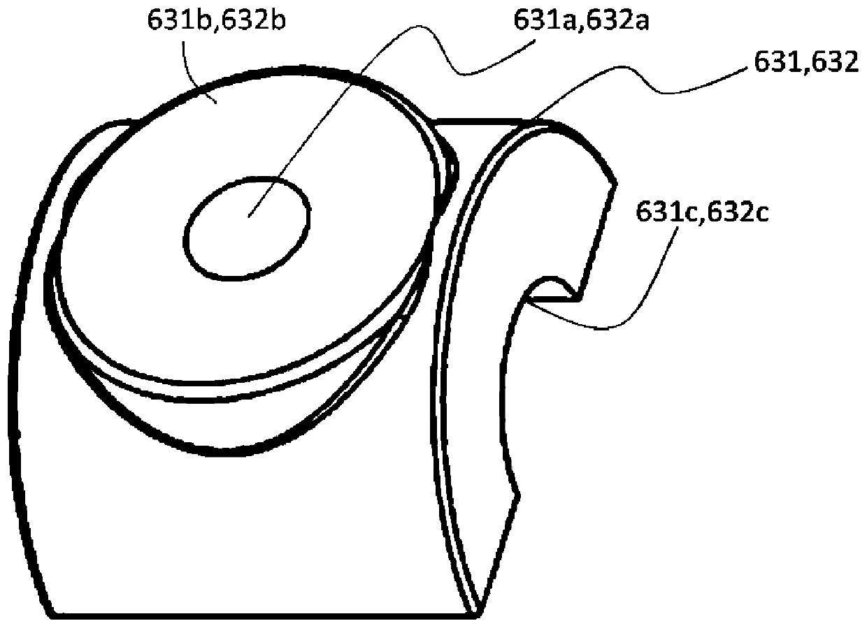
[0038] Below, based on Figure 7 Embodiment 2 of the present invention will be described. Additionally, for Figure 1 to Figure 6 The same or corresponding parts are marked with the same symbols, and their explanations are omitted. In Embodiment 2, the diameters of the through holes through which the stud bolts pass are different. Figure 7 It is a perspective view which shows the arc conductor of Embodiment 2. In the arc conductors 731, 732, when the size of the pedestals 731b, 732b is set to be the same as the size of the pedestals 631b, 632b in Embodiment 1, the diameter of the through holes 731a, 732a is set to be that of the stud bolt 50. more than twice the diameter, so as to increase the proportion of the volume of the through holes 731a, 732a. About inner peripheral surface 731c, 732c, it is the same as inner peripheral surface 631c, 632c in Embodiment 1. Although not shown, the through-holes 14 of the bus bar 10 and the through-holes 731a, 732a of the arc conduct...
Embodiment approach 3
[0044] Embodiment 3 differs from Embodiment 1 or Embodiment 2 in that terminal members 30 , 40 are made of rubber having a hardness higher than that of silicone rubber, such as fluororubber and ethylene propylene rubber. In this case, since the terminal members 30, 40 are not easily deformed, when the insulating plug 20 is inserted into the electrical equipment connection portion 32, 42, the force required for diameter expansion becomes larger, and the insertion and fixation of the insulating plug 20 The surface pressure at the rear insulating interface portion 82 becomes larger. Others are the same as those in Embodiment 1, and thus description thereof will be omitted.
[0045] According to Embodiment 3, the same effect as Embodiment 1 can be obtained.
[0046] In addition, the risk of occurrence of insulation failure can be further reduced. More specifically, since the terminal member is made of hard rubber such as fluororubber and ethylene propylene rubber, the surface pr...
PUM
 Abstract
Description
Claims
Application Information
 - R&D
- Intellectual Property
- Life Sciences
- Materials
- Tech Scout
- Unparalleled Data Quality
- Higher Quality Content
- 60% Fewer Hallucinations
Browse by: Latest US Patents, China's latest patents, Technical Efficacy Thesaurus, Application Domain, Technology Topic, Popular Technical Reports.
© 2025 PatSnap. All rights reserved.Legal|Privacy policy|Modern Slavery Act Transparency Statement|Sitemap|About US| Contact US: help@patsnap.com