Submersible electric pump mounting base

A submersible electric pump and mounting seat technology, applied in the direction of the pump, the components of the pumping device for elastic fluid, the pump element, etc., can solve the problems of complicated operation, impact, pump body or personal injury, etc., and achieve simple installation and operation. , Reduce the impact force and ensure the effect of fixed position

Inactive Publication Date: 2020-02-07
衡阳市大力成泵业制造有限责任公司
View PDF13 Cites 1 Cited by
  • Summary
  • Abstract
  • Description
  • Claims
  • Application Information

AI Technical Summary

Problems solved by technology

[0002] Because of its compact structure, light weight, and convenient installation, use and transfer, submersible electric pumps have been widely used in actual production and life; in the prior art, when installing a submersible electric pump, one person usually needs to grasp the electric pump and It is not only cumbersome to operate, but also easy to cause damage to the pump body or people due to impact when the electric pump is placed during the installation process.

Method used


Image

  • Submersible electric pump mounting base
  • Submersible electric pump mounting base
  • Submersible electric pump mounting base

Examples


Embodiment 1

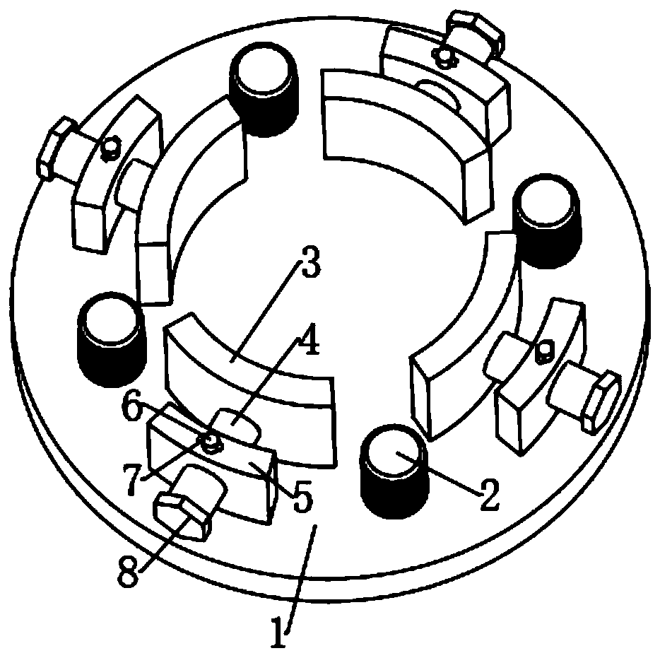
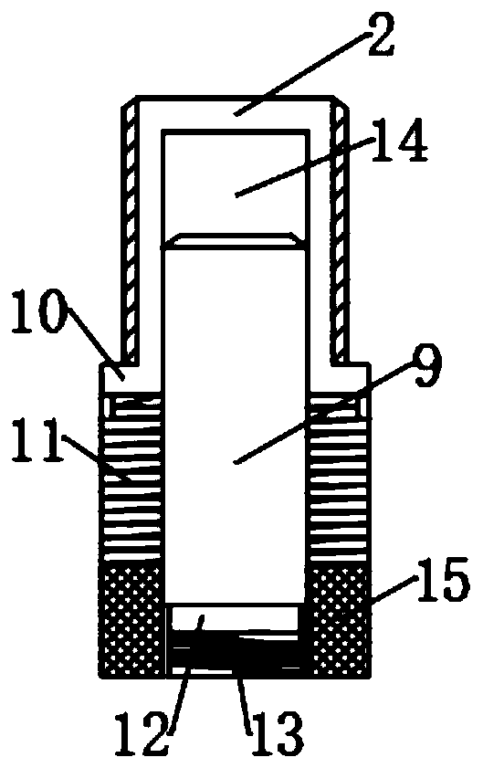
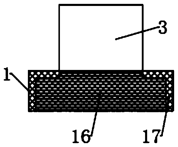
[0020] see Figure 1-3 , a submersible electric pump installation seat, including a workbench 1, the cross section of the workbench 1 is circular, and the upper end surface of the workbench 1 is evenly provided with a plurality of arc-shaped fixing plates 3, and the fixing plates 3 deviate from the center of the workbench 1 An operating mechanism is arranged on one side, and the fixed plate 3 can move back and forth to the center of the workbench 1 through the operating mechanism to fix the submersible electric pump; a plurality of positioning pins 2 are evenly arranged on the periphery of the interval area of ​​the fixed plate 3, and the positioning The pin 2 is provided with a damping mechanism. The specific structure of the operating mechanism is not limited. Preferably, in this embodiment, the operating mechanism includes a limit plate 5, which is arranged on the side of the fixed plate 3 away from the center of the workbench 1. The limit plate The central position of 5 i...

Embodiment 2

[0029] see Figure 4 , in embodiment 1, since the positioning pin 2 is clamped with the lower end of the submersible pump to determine the installation position of the pump body, it is necessary to ensure that the pump body is located at the center of the workbench 1 during the clamping process, so the operation is inconvenient; therefore, This embodiment is improved on the basis of Embodiment 1. The improvement is: a positioning column 18 is arranged at the center of the workbench 1, and the positioning column 18 matches the shape of the inner cavity of the pump body so as to facilitate confirmation of the placement of the pump body Position, improve the installation efficiency of the pump body.


PUM


Abstract

The invention discloses a submersible electric pump mounting base which comprises a workbench. The cross section of the workbench is in a circular shape, a plurality of arc-shaped fixing plates are evenly distributed at the upper end face of the workbench, and an operation mechanism is distributed at the sides, away from the center of the workbench, of the fixing plates. A plurality of positioningpins are evenly distributed at the peripheries of spacer regions of the fixing plates, and damping mechanisms are arranged inside the positioning pins. According to the submersible electric pump mounting base, by evenly distributing the positioning pins matched with the bottom face of a pump body, the mounting position of a submersible electric pump is determined, and buffer mechanisms are arranged inside the positioning pins, so that impact force of the pump body is lowered in the pump body mounting process, the pump body is mounted more stably and safely, and damage caused to the pump bodyis reduced. In addition, the arc-shaped fixing plates evenly distributed on the workbench can better fit the side face of the pump body, the fixing effect of the pump body is ensured, cushions are arranged at the inner sides of the fixing plates, and the surface of the pump body can be effectively protected.

Description

technical field [0001] The invention relates to the technical field of electric pumps, in particular to a mounting seat for a submersible electric pump. Background technique [0002] Because of its compact structure, light weight, and convenient installation, use and transfer, submersible electric pumps have been widely used in actual production and life; in the prior art, when installing a submersible electric pump, one person usually needs to grasp the electric pump and It is not only complicated to operate, but also easy to cause damage to the pump body or people due to impact when the electric pump is placed during the installation process. Therefore, it is necessary to improve the prior art. Contents of the invention [0003] The purpose of the present invention is to provide a submersible electric pump mounting base to solve the problems raised in the above-mentioned background technology. [0004] To achieve the above object, the present invention provides the fol...

Claims


Application Information

Patent Timeline
Patent Type & Authority Applications(China)
IPC IPC(8): F04D29/60F04D29/66
CPCF04D29/605F04D29/669
Inventor 阳志华黎瑞胡轩诚
Owner 衡阳市大力成泵业制造有限责任公司
Why Eureka
Try Eureka