Grounding connecting piece in electrical cabinet

A technology of grounding connectors and electrical cabinets, applied in the direction of grounding devices, etc., can solve the problems of affecting the closing of cabinet doors, affecting the electrical connection between cabinet body and cabinet door, and affecting the quality of electrical switch cabinets, so as to facilitate installation and use, and realize real-time positioning Effect

Inactive Publication Date: 2020-02-07
咸宁恒舟信息科技有限公司
View PDF7 Cites 0 Cited by
  • Summary
  • Abstract
  • Description
  • Claims
  • Application Information

AI Technical Summary

Problems solved by technology

The outer wall of the existing cabinet body and the outer wall of the cabinet door are generally sprayed with paint or plastic, which affects the electrical connection between the cabinet body and the cabinet door. In order to improve the safety of the electrical switch cabinet, generally a Cooperate with the conductive connector for grounding. The existing conductive connector is generally a wire, and the two ends of the wire are fixedly connected with ring-shaped cold-pressed terminals. The connection between the cold-pressed terminal and the cabinet door or cabinet is realized by screws. , but its wires will hang down and be inserted between the gap between the cabinet door and the cabinet body, which will affect the closing of the cabinet door; and the wire connection needs to use screws or bolts, and corresponding jacks need to be opened on the cabinet door or cabinet body, which will affect the closing of the cabinet door. The quality of electrical switchgear

Method used


Image

  • Grounding connecting piece in electrical cabinet
  • Grounding connecting piece in electrical cabinet
  • Grounding connecting piece in electrical cabinet

Examples


Embodiment

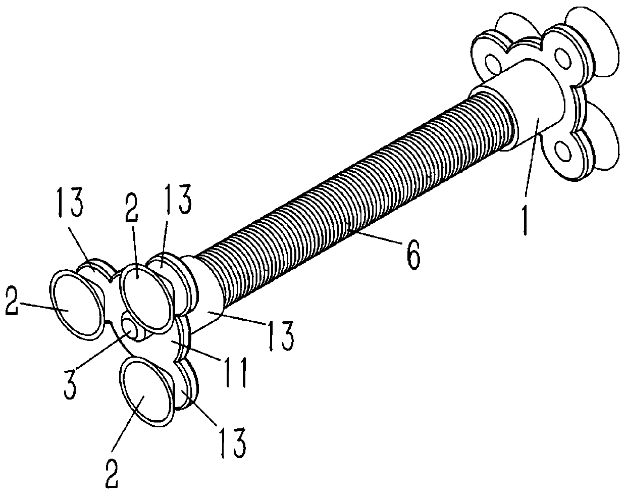
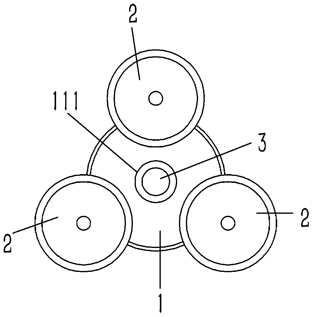
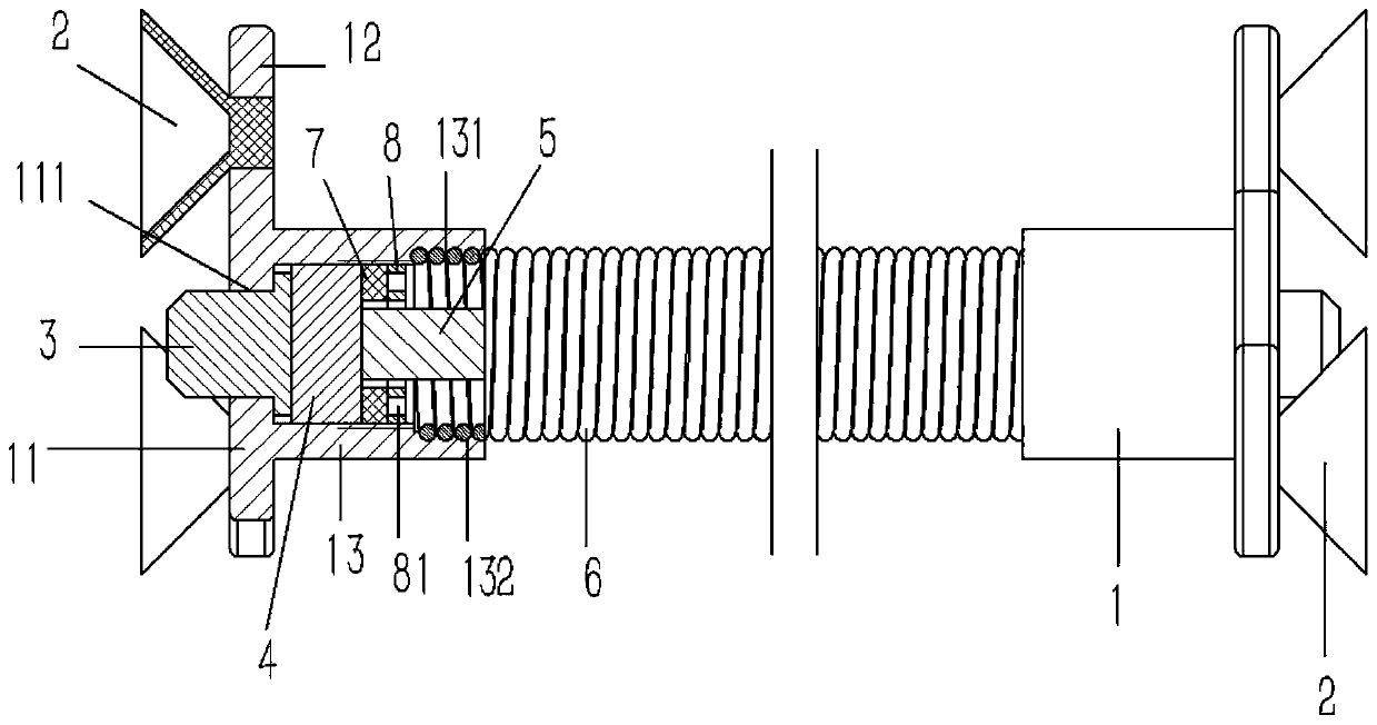
[0019] Example: see Figures 1 to 3 As shown, a ground connector in an electrical cabinet includes a fixed seat 1, and the fixed seat 1 includes a circular base 11. Several circular connecting seats 12 are formed on the outer wall of the base 11, and the connecting seats 12 are fixed A suction cup 2 is connected; a socket 111 is formed in the center of the base 11, and a T-shaped conductive contact 3 is inserted into the socket 111, and a socket connected to the socket 111 is formed on one end surface of the base 11. The ring sleeve 13 is inserted with a conductive block 4 inside the ring sleeve 13, and the conductive block 4 is fixed at both ends of the flexible conductive iron wire 5; the two side walls of the conductive block 4 are respectively pressed against the conductive contact 3 and the external thread The sleeve 8 and the external thread sleeve 8 are inserted and sleeved on the flexible conductive iron wire 5 and screwed in the ring sleeve 13 of the fixed seat 1; the...


PUM


Abstract

The invention discloses a grounding connecting piece in an electrical cabinet, which comprises a fixed seat. The fixed seat comprises a circular base, a plurality of circular connecting seats are formed on the outer wall of the base, and suckers are fixedly connected to the connecting seats; a jack is formed in the center of the base, a T-shaped conductive contact is inserted into the jack, a ringsleeve communicated with the jack is formed on the end surface of one side of the base, a conductive block is inserted into the ring sleeve, and the conductive block is fixed at the two ends of a flexible conductive iron wire; a conductive contact and an external thread sleeve are pressed against the end surfaces of the two side walls of the conductive block respectively, and the external threadsleeve is inserted into the flexible conductive iron wire in a sleeving manner and is in threaded connection with the interior of the ring sleeve of the fixed seat; a spring-shaped protective sleeve is inserted into the flexible conductive iron wire in a sleeved mode, and the two ends of the protective sleeve are inserted and fixed into the ring sleeve of the fixed seat. The use of a cabinet dooris not influenced, the structure of the electrical switch cabinet is not damaged, and the installation and the use are convenient.

Description

technical field [0001] The invention relates to the technical field of electrical connectors, and more specifically relates to a grounding connector in an electrical cabinet. Background technique [0002] The electrical switchgear is a kind of electrical equipment. The external line of the switchgear first enters the main control switch in the cabinet, and then enters the sub-control switch. Each branch is set according to its needs. The main function is to perform power generation, transmission, distribution and power conversion in the power system During the process, switch, control and protect electrical equipment. The components in the switch cabinet are mainly composed of circuit breakers, disconnectors, load switches, operating mechanisms, transformers and various protection devices. The outer wall of the existing cabinet body and the outer wall of the cabinet door are generally sprayed with paint or plastic, which affects the electrical connection between the cabinet...

Claims


Application Information

Patent Timeline
IPC IPC(8): H02B1/16
CPCH02B1/16
Inventor 秦小燕
Owner 咸宁恒舟信息科技有限公司
Why Eureka
Try Eureka