
High Precision Current Transformer

A current transformer, high-precision technology, applied in the field of transformers, can solve the problems of full load overheating, small current value at the measuring end, low measurement accuracy, etc., to achieve the effect of easy assembly

Active Publication Date: 2022-04-05
庐江和润科技有限公司
View PDF0 Cites 0 Cited by
  • Summary
  • Abstract
  • Description
  • Claims
  • Application Information

AI Technical Summary

Problems solved by technology

[0003] Due to the large range of current variation, the secondary winding and primary winding are required to have a large turns ratio suitable for the current peak, but this will cause the secondary current to be reduced by a large factor when the current valley value or close to the valley value. The current value of the measurement terminal is small, resulting in low measurement accuracy. If a small turn ratio is set, although the measurement accuracy can be improved, the rated primary current cannot reach the current peak value, resulting in insufficient measurement range and full-load overheating.

Method used


Image

  • High Precision Current Transformer
  • High Precision Current Transformer
  • High Precision Current Transformer

Examples


Embodiment 1

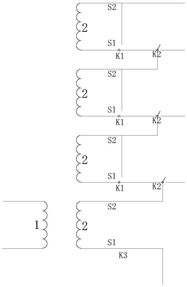
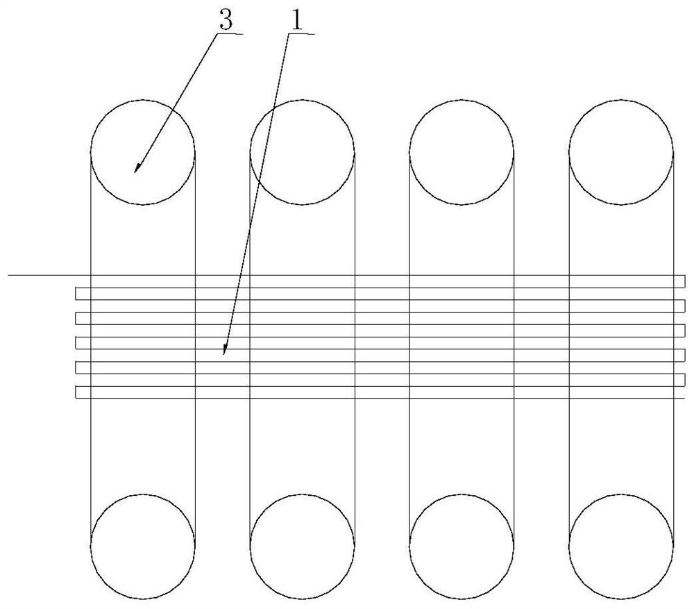
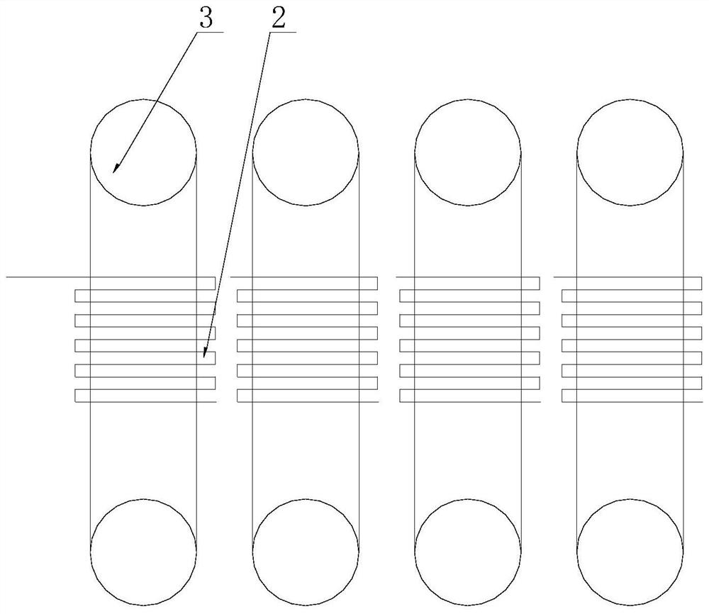
[0032] like Figure 1-6 As shown, the high-precision current transformer includes a primary winding 1 and several secondary windings 2, the primary winding 1 and several secondary windings 2 form several winding units, and each winding unit includes a secondary winding 2, several Two secondary windings 2 are connected in series or disconnected through the disconnect switch K2.

[0033] Several secondary windings 2 are respectively wound on each iron core 3 , the number of iron cores 3 is the same as that of the secondary windings 2 , and the primary winding 1 is wound on several iron cores 3 .

[0034] Each secondary winding 2 is provided with two outlets, namely the first outlet S1 and the second outlet S2;

[0035] The first outgoing terminal S1 of one secondary winding 2 of two adjacent secondary windings 2 and the second outgoing terminal S2 of the other secondary winding 2 are jointly connected to the moving end of the disconnecting switch K2, and the non-conducting term...

Embodiment 2

[0055] like Figure 7 As shown, on the basis of Embodiment 1, a main terminal switch K3 is provided between the first outlet terminal S1 of the first secondary winding 2 of several secondary windings 2 and the secondary winding 2, and the main terminal switch K3 The moving end is connected to the secondary winding 2 , the non-moving end is connected to a short-circuit wire, and the other end of the short-circuit wire is connected to the second outlet S2 of the secondary winding 2 . The main terminal switch K3 short-circuits the secondary winding 2 at the first terminal, so that the entire secondary winding 2 is disconnected from the detection module. As a safety guarantee measure, the high voltage hazard caused by the complete open circuit of the secondary winding 2 is avoided.


PUM


Abstract

The invention relates to a high-precision current transformer. The high-precision current transformer includes a primary winding and several secondary windings. The primary winding and several secondary windings form several winding units, and each winding unit includes a secondary winding. , several secondary windings are connected in series or disconnected through a circuit breaker; the two ends of the primary winding are respectively connected to two main input terminals; Adding secondary windings connected in series will increase the turns ratio accordingly, so that the secondary current will be in a suitable range, and will not be too small, nor will it lead to full load. It is worth vigorously promoting.

Description

technical field [0001] The invention belongs to the technical field of transformers, in particular to high-precision current transformers. Background technique [0002] Transformer, also known as instrument transformer, is a general term for current transformer and voltage transformer. It can change high voltage into low voltage and high current into small current for measurement or protection system. Its function is mainly to convert high voltage or high current into standard low voltage (100V) or standard small current (5A or 1A, both refer to rated value) in proportion, so as to realize the standardization and miniaturization of measuring instruments, protection equipment and automatic control equipment. change. At the same time, the transformer can also be used to isolate the high-voltage system to ensure the safety of people and equipment. [0003] Due to the large range of current variation, the secondary winding and primary winding are required to have a large turn...

Claims


Application Information

Patent Timeline
Patent Type & Authority Patents(China)
IPC IPC(8): H01F27/26H01F27/28H01F27/40H01F38/30
CPCH01F27/28H01F27/40H01F27/2895H01F27/263H01F38/30H01F2038/305
Inventor 潘文韬吴昌松
Owner 庐江和润科技有限公司
Learn More