A Magnetically Coupled Single-Phase High Gain Bridgeless Power Factor Correction Circuit

A technology of power factor correction and high gain, which is applied in the field of magnetically coupled single-phase high-gain bridgeless power factor correction circuit, can solve the problems of large switch tube loss, reduced overall machine efficiency, and increased switch tube voltage stress, etc., to achieve The effect of low voltage stress, improving the efficiency of the whole machine, and reducing the conduction voltage drop

Active Publication Date: 2016-05-04
SOUTH CHINA UNIV OF TECH
View PDF3 Cites 0 Cited by
  • Summary
  • Abstract
  • Description
  • Claims
  • Application Information

AI Technical Summary

Problems solved by technology

At present, the widely used single-phase power factor correction circuit is composed of a diode rectifier bridge plus Boost, Flyback and other DC / DC converters. Due to the common conduction voltage drop of the diode rectifier bridge, the efficiency of the whole machine is reduced.
In addition, the boost ratio of the traditional single-phase Boost power factor correction circuit is limited by the duty cycle, while the single-phase Flyback power factor correction circuit generally works in the current discontinuous mode, the loss of the switching tube is large, and the leakage inductance will cause the switching tube The voltage stress increases

Method used


Image

  • A Magnetically Coupled Single-Phase High Gain Bridgeless Power Factor Correction Circuit
  • A Magnetically Coupled Single-Phase High Gain Bridgeless Power Factor Correction Circuit
  • A Magnetically Coupled Single-Phase High Gain Bridgeless Power Factor Correction Circuit

Examples


Embodiment Construction

[0026] The present invention will be further described below in conjunction with specific examples.

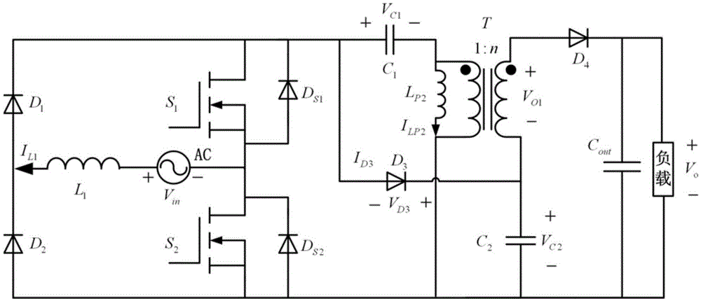
[0027] see figure 1 As shown, the magnetic coupling type single-phase high-gain bridgeless power factor correction circuit described in this embodiment includes an AC input power supply AC, a first inductor L 1 , the first diode D 1 , the second diode D 2 , the first switching tube S 1 and its antiparallel diode D S1 , the second switch tube S 2 and its antiparallel diode D S2 , the first capacitance C 1 , the third diode D 3 , a transformer T with a primary-to-secondary turn ratio of 1:n, and a second capacitor C 2 , the fourth diode D 4 , the output capacitance C out ; Wherein, one end of the AC input power supply AC and the first inductance L 1 One end is connected, and the other end is respectively connected with the first switching tube S 1 source and the second switch S 2 The drain connection; the first inductance L 1 The other end of the first diode D 1 a...


PUM


Abstract

The invention discloses a magnetic coupling type single-phase high-gain bridge-free power factor correction circuit. The circuit comprises an alternating current input power supply, a first inductor, a first diode, a second diode, a first switching tube, an antiparallel diode of the first switching tube, a second switching tube, an antiparallel diode of the second switching tube, a first capacitor, a third diode, a transformer, a second capacitor, a fourth diode and an output capacitor. The alternating current input power supply is connected with the first inductor, the first switching tube and the second switching tube. The first inductor is connected with the first diode and the second diode. The first diode is connected with the first switching tube, the first capacitor and the third diode. The second diode is connected with the second switching tube, the primary side of the transformer, the second capacitor, the output capacitor and a load. The first capacitor is connected with the primary side of the transformer. The auxiliary side of the transformer is connected with the third diode and the second capacitor. The auxiliary side of the transformer is connected with the fourth diode. The fourth diode is connected with the output capacitor and the load. The magnetic coupling type single-phase high-gain bridge-free power factor correction circuit has high working efficiency, and the adjusting range of output voltages is wider.

Description

technical field [0001] The invention relates to the technical field of single-phase power factor correction, in particular to a magnetic coupling type single-phase high-gain bridgeless power factor correction circuit. Background technique [0002] It is known in the industry that in order to reduce harmonic pollution to the power grid, power electronic devices with a power greater than 75W must have a power factor correction function. At present, the widely used single-phase power factor correction circuit is composed of a diode rectifier bridge plus Boost, Flyback and other DC / DC converters. Due to the common conduction voltage drop of the diode rectifier bridge, the efficiency of the whole machine is reduced. In addition, the step-up ratio of the traditional single-phase Boost power factor correction circuit is limited by the duty cycle, while the single-phase Flyback power factor correction circuit generally works in the current discontinuous mode, the loss of the switchi...

Claims


Application Information

Patent Timeline
Patent Type & Authority Patents(China)
IPC IPC(8): H02M1/42
CPCY02B70/10Y02P80/10
Inventor 丘东元周丽萍张波肖文勋黄子田
Owner SOUTH CHINA UNIV OF TECH
Why Eureka
Try Eureka