Display panel and display device

A technology of display panel and display area, applied in the direction of identification devices, instruments, diodes, etc., can solve the problems that the front camera integration cannot be solved well, and the display panel cannot display information in the slotted or punched area, so as to achieve a full-screen display. Design and improve the effect of display area

Active Publication Date: 2020-02-11
KUNSHAN GO VISIONOX OPTO ELECTRONICS CO LTD
View PDF3 Cites 8 Cited by
  • Summary
  • Abstract
  • Description
  • Claims
  • Application Information

AI Technical Summary

Problems solved by technology

At present, devices such as fingerprint recognition and earpieces can be well integrated under the display panel, but the integration of the front camera of electronic products still cannot be well solved.
[0003] For the integration of the front camera, the current solution is to dig a groove or punch a hole in the position corresponding to the camera on the display panel. However, it will cause the problem that information cannot be displayed in the grooved or punched area of ​​the display panel.

Method used


Image

  • Display panel and display device
  • Display panel and display device
  • Display panel and display device

Examples


Embodiment Construction

[0025] The features and exemplary embodiments of various aspects of the present invention will be described in detail below. In order to make the objectives, technical solutions and advantages of the present invention more clear, the present invention will be further described in detail below with reference to the accompanying drawings and specific embodiments. It should be understood that the specific embodiments described herein are only configured to explain the present invention, and are not configured to limit the present invention. It will be apparent to those skilled in the art that the present invention may be practiced without some of these specific details. The following description of the embodiments is only intended to provide a better understanding of the present invention by illustrating examples of the invention.

[0026] It should be noted that, in this document, relational terms such as first and second are only used to distinguish one entity or operation from...


PUM


Abstract

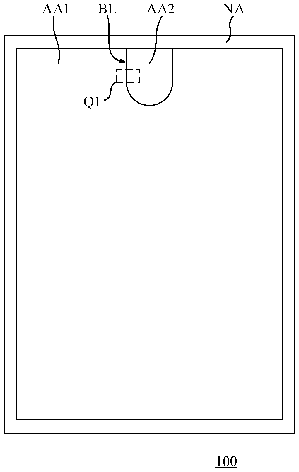
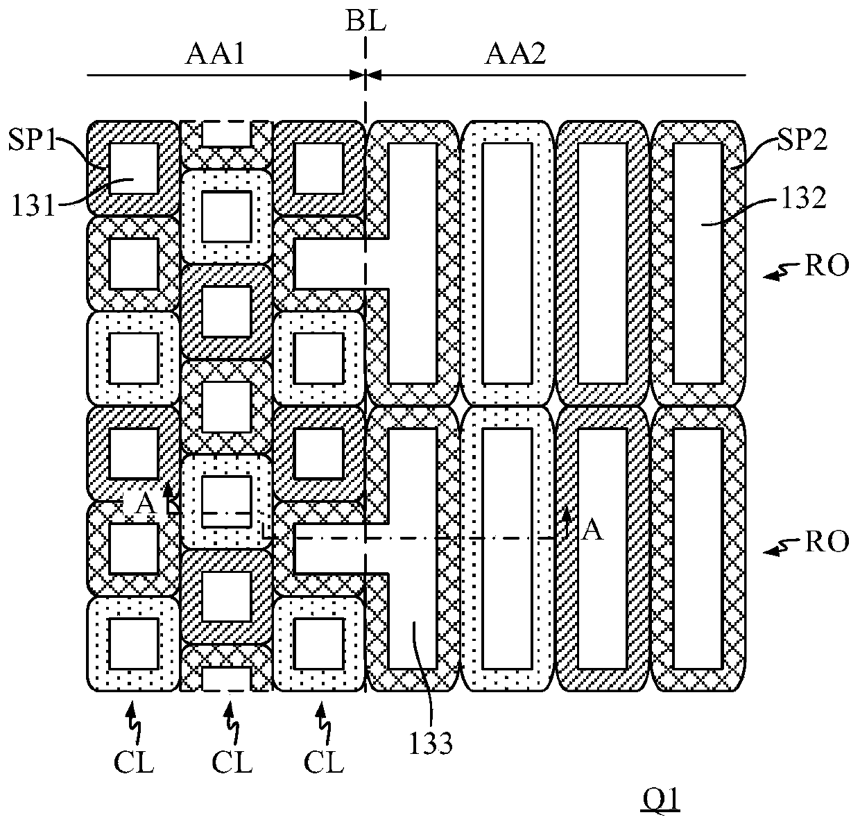
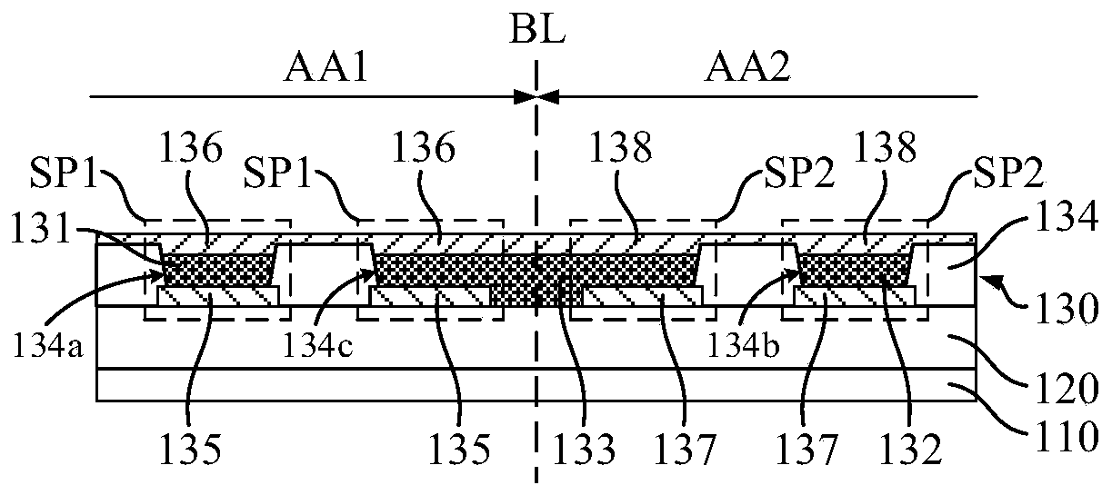
The invention discloses a display panel and a display device. The display panel comprises a first display area, a second display area and a boundary, wherein the light transmittance of the second display area is larger than that of the first display area. The display panel comprises a substrate and a pixel layer. The pixel layer comprises first sub-pixels and second sub-pixels, wherein the first sub-pixel is located in the first display area, and the first sub-pixel comprises a first light-emitting structure; the second sub-pixel is located in the second display area, the second pixel arrangement structure of the second sub-pixel is different from the first pixel arrangement structure of the first sub-pixel, the second sub-pixel comprises a second light-emitting structure, and the second light-emitting structure of the second sub-pixel adjacent to the boundary and the first light-emitting structure of the adjacent first sub-pixel in the same color are interconnected to form an interconnected light-emitting structure. According to the display panel provided by the embodiment of the invention, the non-light-emitting area between the second sub-pixel and the first sub-pixel which areadjacent to the boundary is prevented from being too wide, so that dark lines which are easy to appear at the boundary when the display panel displays are eliminated.

Description

technical field [0001] The present invention relates to the field of display, in particular to a display panel and a display device. Background technique [0002] High screen-to-body ratio is the latest development direction of smart electronic products. In order to increase the screen-to-body ratio, various sensors on the front of electronic products need to be integrated under the display panel. At present, devices such as fingerprint recognition and earpieces can be well integrated under the display panel, but the integration of the front camera of electronic products still cannot be well solved. [0003] For the integration of the front camera, the current solution is to notch or punch a hole on the display panel at the position corresponding to the camera. However, it will cause the problem that information cannot be displayed in the notch or hole area of ​​the display panel. SUMMARY OF THE INVENTION [0004] The present invention provides a display panel and a disp...

Claims


Application Information

Patent Timeline
IPC IPC(8): H01L27/32G09F9/33
CPCG09F9/33H10K59/352H10K59/131H10K59/80521H10K59/65H10K59/80515H10K59/353H10K59/122H10K59/121
Inventor 张兵
Owner KUNSHAN GO VISIONOX OPTO ELECTRONICS CO LTD
Why Eureka
Try Eureka