Electric connector

A technology of electrical connectors and docking slots, applied in the direction of connections, circuits, and parts of connection devices, can solve the problems of inconvenient use, inconvenient use, and impact on portability, and meet the needs of different power charging and strengthen the market Competitiveness, cost-saving effects

Pending Publication Date: 2020-02-11
DONGGUAN YUQIU ELECTRONICS CO LTD
View PDF0 Cites 0 Cited by
  • Summary
  • Abstract
  • Description
  • Claims
  • Application Information

AI Technical Summary

Problems solved by technology

[0003] When the current electrical connector is used for charging, one electrical connector can only output one kind of charging power, and the charging power is fixed and cannot be freely selected, which makes it extremely inconvenient to use
If it is necessary to charge multiple products with different power, multiple different electrical connectors must be used, which not only increases the cost of use, but also affects portability. It is not convenient to use and causes great trouble to users.

Method used


Image

  • Electric connector
  • Electric connector
  • Electric connector

Examples


Embodiment 1

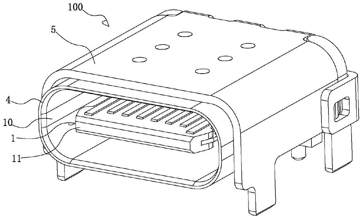
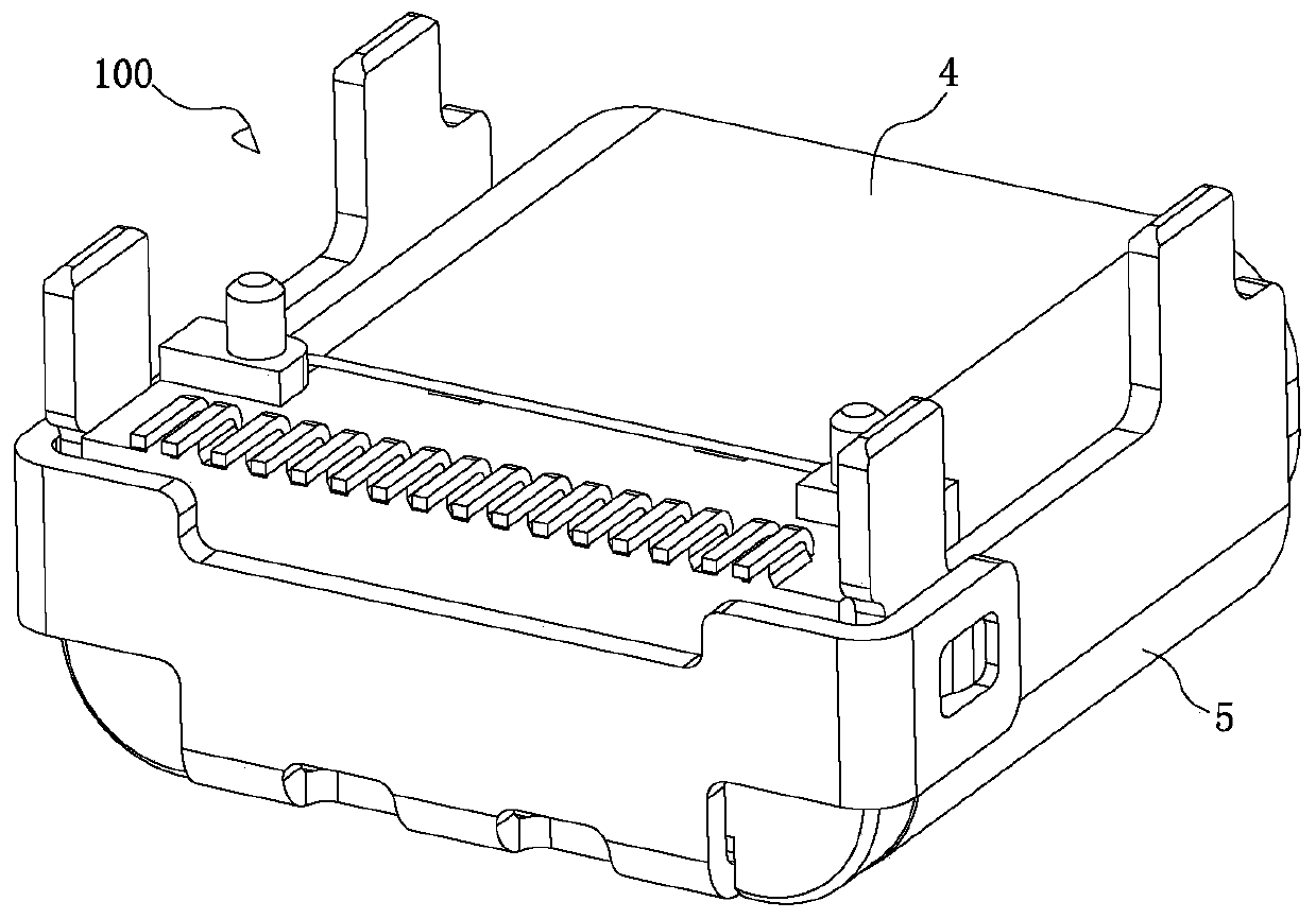
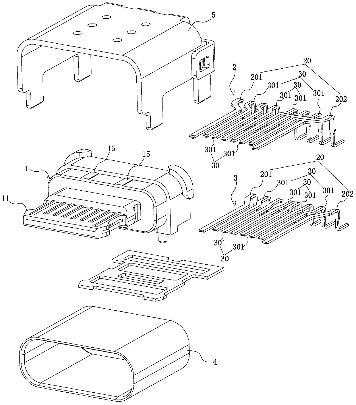
[0036] see Figure 1-5 , 10-15, is an electrical connector, which includes a female base 100 and at least two types of male bases 600 adapted to the female base 100 and capable of charging at different powers, the female base 100 is provided with a first A ground terminal set 20 and at least two sets of first power terminal sets 30 arranged beside the first ground terminal set 20 and capable of charging at different powers; each male header 600 is provided with a first ground terminal set 20 The adapted second ground terminal group 70 and a group of second power terminal groups 60 that are arranged beside the second ground terminal group 70 and can realize different power charging, and the second power terminal group 60 is in the female base 100 A set of the first power terminal set 30 is adapted, wherein the installation position of the second power terminal set 60 in each male head 600 is different. The present invention is used as a charging connector. Since the female base ...

Embodiment 2

[0049] Combine Figure 6-7 As shown, the difference between the second embodiment and the first embodiment above is that the first pins of all terminals in the first terminal module 2 are of patch structure, and the first pins are attached to the insulating seat 1 On the first pad 13 formed at the rear of the lower end surface; the second pins of all the terminals in the second terminal module 3 have a patch structure, and the second pins are attached to the lower end surface of the insulating seat 1 Is formed on the second cushion platform 14 and arranged in two rows with the first pins.

[0050] A first limiting protrusion 161 and a second limiting protrusion 162 are respectively formed on both sides of the lower end surface of the insulating seat 1, and the first limiting protrusion 161 and the second limiting protrusion 162 are respectively formed with The first positioning post 163 and the second positioning post 164 that are inserted and positioned with the PCB are formed w...

Embodiment 3

[0053] Combine Figure 8-9 As shown, the third embodiment is different from the above-mentioned second embodiment in that: the first pins of all the terminals in the first terminal module 2 have a pin structure and protrude from the first pin in one or two rows. Outside the lower end surface of the insulating seat 1; the second pins of all terminals in the second terminal module 3 are of a patch structure, and the second pins are attached to the second pad formed behind the lower end surface of the insulating seat 1 On 14, the first pin and the second pin are arranged in two or three rows. The lower end surface of the metal inner shell 4 is formed with a plurality of raised bumps 42 for contact with the PCB.

[0054] Except for the above, the other structure of the third embodiment is the same as the structure of the second embodiment above, and can achieve the technical effects as described in the first embodiment, which will not be repeated here.


PUM


Abstract

The invention discloses an electric connector. The electric connector comprises a female seat and at least two male heads which are matched with the female seat and can realize charging with differentpower. A first grounding terminal group and at least two groups of first power terminal groups which are arranged beside the first grounding terminal group and can realize charging with different power are arranged in the female seat. A second grounding terminal group matched with the first grounding terminal group and a second power terminal group capable of achieving charging with different power are arranged in each male head. The second power terminal group is matched with one first power terminal group in the female seat, and installation positions of the second power terminal groups ineach male head are different. The electric connector is used as a charging connector, the female seat carries a plurality of power specifications at the same time, and the different male heads are designed according to different power specifications so that functions of one female seat to multiple male heads and different power charging are achieved, the different male heads can be freely selectedto be in butt joint with the female seat, and the electric connector can be flexibly and conveniently used.

Description

Technical field: [0001] The invention relates to the technical field of connector products, in particular to an electrical connector. Background technique: [0002] The main supporting fields of electrical connectors include transportation, communication, network, IT, medical treatment, home appliances, military electronic products, etc. The rapid development of product technology in supporting fields and the rapid growth of the market have strongly driven the development of connector technology . So far, electrical connectors have developed into a series and specialized products with complete product categories, rich varieties and specifications, diverse structure types, subdivision of professional directions, obvious industry characteristics, and standard system specifications. [0003] When the current electrical connector is used for charging, one electrical connector can only output one type of charging power, and the charging power is fixed and cannot be freely selected, res...

Claims


Application Information

Patent Timeline
Patent Type & Authority Applications(China)
IPC IPC(8): H01R27/00H01R13/20H01R13/627H01R13/629
CPCH01R13/20H01R13/627H01R13/629H01R27/00
Inventor 彭文福吴斗风蔡上升陈善君朱兵雷邹文俊
Owner DONGGUAN YUQIU ELECTRONICS CO LTD
Why Eureka
Try Eureka