An environmental protection sewage pipeline maintenance equipment

An environmentally friendly sewage and pipeline technology, applied in the direction of load suspension components, lifting devices, transportation and packaging, etc., can solve the problems of hidden safety hazards in pipelines, easy impact on workers, shaking, etc.

Active Publication Date: 2021-06-04
抚州圣昆仑环境科技有限公司
View PDF12 Cites 0 Cited by
  • Summary
  • Abstract
  • Description
  • Claims
  • Application Information

AI Technical Summary

Problems solved by technology

[0003] However, there are the following problems in the process of using a crane to pull out the pipeline: a. In the traditional pipeline pulling operation, the outside of the pipeline is fixed and locked, and the crane is used to pull it out upwards, and the pipeline is squeezed by the soil. Its own specific gravity increases, and when the locked pipe is lifted upwards with brute force, it is easy to deform the outer wall of the pipe, resulting in damage to the pipe
b. When using a crane to lift the pipeline, it is necessary to fix the pipeline with the help of clamps. When working on different types of pipelines, it is necessary to manually adjust according to the pipeline model, and the stability of the manual use of clamps to fix the pipeline is poor. There are safety hazards in the lifting and pulling operation, which reduces the efficiency of pipe pulling
c. Due to the different softness of the soil during the extraction of the pipeline, there will be a change in the extraction speed when the pipeline is lifted upwards. The crane adopts the rope traction and stretching method. When the speed changes, the tension of the rope itself will change accordingly. If there is a change, it is easy to cause the lifted pipeline to slide down, and when the pipeline is pulled out of the soil, it will shake, etc., and it is easy to hit the operator and other technical problems

Method used


Image

  • An environmental protection sewage pipeline maintenance equipment
  • An environmental protection sewage pipeline maintenance equipment
  • An environmental protection sewage pipeline maintenance equipment

Examples


Embodiment Construction

[0025] The embodiments of the present invention will be described in detail below with reference to the accompanying drawings, but the present invention can be implemented in many different ways defined and covered by the claims.

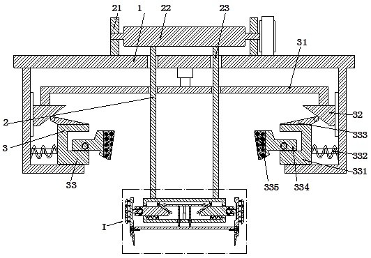
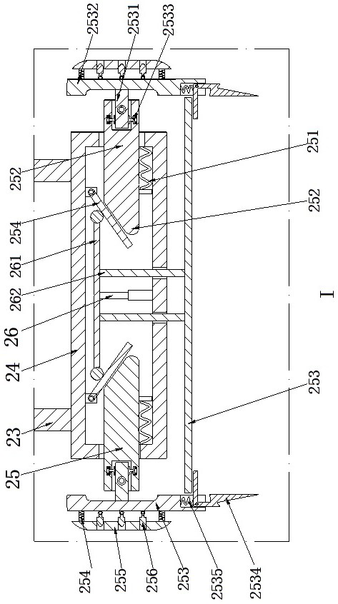
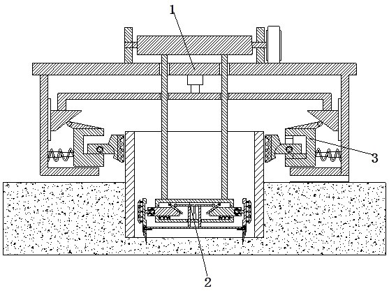
[0026] Such as Figure 1 to Figure 3 As shown, an environmental protection sewage pipeline inspection and maintenance equipment includes a fixed base frame 1, a pulling mechanism 2 is arranged on the fixed base frame 1, and an auxiliary mechanism 3 is arranged at the lower end of the fixed base frame 1.

[0027] Described pulling mechanism 2 comprises the threading hole that is arranged on the fixed base frame 1, and fixed bracket 21 is installed on the fixed base frame 1, is provided with winding roller 22 through bearing between the inner wall of fixed bracket 21, and one end of winding roller 22 Connected to the motor, the motor is installed on the fixed base frame 1, the wire rope 23 is wound on the winding roller 22, the lower end of the steel ...


PUM


Abstract

The invention relates to an environment-friendly sewage pipeline inspection and maintenance equipment, which comprises a fixed base frame, a pulling mechanism is arranged on the fixed base frame, and an auxiliary mechanism is arranged at the lower end of the fixed base frame. The present invention can solve the following problems existing in the process of using a crane to pull out a pipeline: a. The strength of the pipeline being squeezed by the soil and its own specific gravity increase, and it is easy to lift the locked pipeline upwards with brute force Deform the outer wall of the pipe, resulting in damage to the pipe. b. When using a crane to lift the pipeline, it is necessary to fix the pipeline with the help of clamps. When working on different types of pipelines, it is necessary to manually adjust according to the pipeline model, and the stability of the manual use of clamps to fix the pipeline is poor. c. It is easy to cause the lifted pipeline to slide down. When the pipeline is pulled out of the soil, it will shake, etc., and it is easy to hit the operator and other technical problems.

Description

technical field [0001] The invention relates to the technical field of environmental protection equipment, in particular to maintenance equipment for environmental protection sewage pipelines. Background technique [0002] Sewage pipes are commonly used tools in sewage treatment operations. In sewage treatment operations, sewage pipes need to be replaced and repaired regularly. When repairing and replacing sewage pipes, it is necessary to remove the pipes that are vertically inserted into the soil, especially for vertically inserted into the soil. The internal pipes need to use equipment such as cranes to pull out the pipes fixed with clamps from the soil. [0003] However, there are the following problems in the process of using a crane to pull out the pipeline: a. In the traditional pipeline pulling operation, the outside of the pipeline is fixed and locked, and the crane is used to pull it out upwards, and the pipeline is squeezed by the soil. Its own specific gravity in...

Claims


Application Information

Patent Timeline
Patent Type & Authority Patents(China)
IPC IPC(8): B66F11/00B66C1/30
CPCB66C1/30B66F11/00
Inventor 郭亚征
Owner 抚州圣昆仑环境科技有限公司
Why Eureka
Try Eureka