A detector of relay and driver chip

A technology for driving chips and relays, applied in the field of detection, can solve the problems of poor load performance of relay driving chips and unstable test equipment, and achieve the effect of convenient detection

Active Publication Date: 2021-12-28
SHENZHEN STS MICROELECTRONICS CO LTD
View PDF11 Cites 0 Cited by
  • Summary
  • Abstract
  • Description
  • Claims
  • Application Information

AI Technical Summary

Problems solved by technology

Relay aging and driver chip load performance deterioration are the most important factors leading to instability of test equipment

Method used


Image

  • A detector of relay and driver chip
  • A detector of relay and driver chip
  • A detector of relay and driver chip

Examples


Embodiment Construction

[0038] Below, the present invention will be further described in conjunction with the accompanying drawings and specific implementation methods. It should be noted that, under the premise of not conflicting, the various embodiments described below or the technical features can be combined arbitrarily to form new embodiments. .

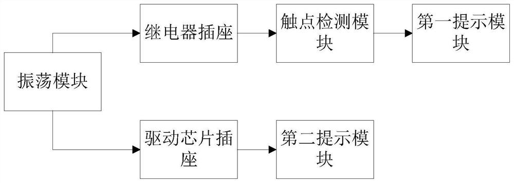
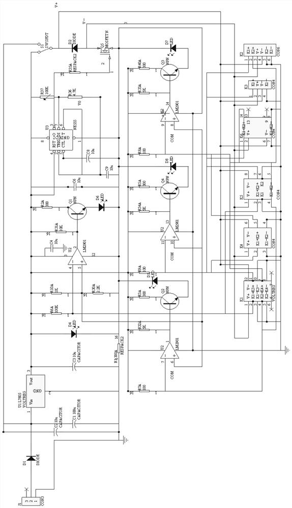
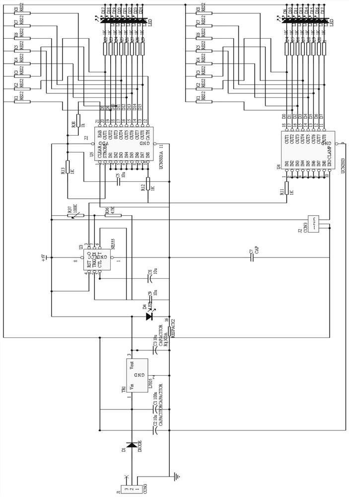
[0039] Such as figure 1 with figure 2 As shown, this embodiment provides a detector for a relay and a driver chip, including an oscillation module, a relay socket, a contact detection module, a driver chip socket, a detection relay, a first prompt module and a second prompt module;

[0040] The oscillating module is electrically connected to the relay socket and the driver chip socket, and the oscillating module is used to generate periodic pulse signals to trigger the operation of the relay to be detected installed at the relay socket and / or trigger the operation of the relay installed at the driver chip socket. The driver chip to be tested works; ...


PUM


Abstract

The invention discloses a detector for a relay and a drive chip, comprising an oscillation module, a relay socket, a contact detection module, a drive chip socket, a detection relay, a first prompt module and a second prompt module; the oscillation module and the relay socket The drive chip socket is electrically connected, and the oscillation module is used to generate periodic pulse signals to trigger the operation of the relay to be detected installed at the relay socket and / or trigger the operation of the drive chip to be detected installed at the drive chip socket. The detector of the relay and the driver chip of the present invention can not only realize the independent detection of the performance of the relay and the driver chip, but also realize the parallel detection of the relay and the driver chip; and realize the dynamic detection rather than the static detection of the driver chip, It is convenient for users to detect the actual performance of relays and / or driver chips.

Description

technical field [0001] The invention relates to the technical field of detection, in particular to a detector for a relay and a driving chip. Background technique [0002] Relays and driver chips are common components. Relays used in test equipment require fast response and low contact resistance (within 0.3 ohms). The aging of the relay and the deterioration of the load performance of the driver chip are the most important factors leading to the instability of the test equipment. [0003] At present, the following scheme is disclosed: the scheme with the application number CN201510525411.7, which discloses the relay action time detection circuit and detection method, because the programmable logic device also includes detection of relay normally open or normally closed contact action level state change The program and the program of the recording time length, when it is detected that the relay contact changes from one level state to another level state, the recording time ...

Claims


Application Information

Patent Timeline
Patent Type & Authority Patents(China)
IPC IPC(8): G01R31/327G01R31/28
CPCG01R31/327G01R31/2851
Inventor 米鹏李伟志李伟周杰
Owner SHENZHEN STS MICROELECTRONICS CO LTD
Why Eureka
Try Eureka