
Antenna

An antenna and feeder technology, applied in the field of communication, can solve the problem of high antenna cost and achieve the effect of low cost and simple structure

Pending Publication Date: 2020-02-21
SHENZHEN ANTOP TECH
View PDF0 Cites 0 Cited by
  • Summary
  • Abstract
  • Description
  • Claims
  • Application Information

AI Technical Summary

Problems solved by technology

[0003] The purpose of the present invention is to provide an antenna, aiming to solve the technical problem of high cost of customizing the antenna according to the requirements of different customers for the frequency band

Method used


Image

  • Antenna
  • Antenna
  • Antenna

Examples


Embodiment Construction

[0041] In order to make the object, technical solution and advantages of the present invention clearer, the present invention will be further described in detail below in conjunction with the accompanying drawings and embodiments. It should be understood that the specific embodiments described here are only used to explain the present invention, not to limit the present invention.

[0042] It should be noted that when a component is referred to as being “fixed on” or “disposed on” another component, it may be directly or indirectly on the other component. When an element is referred to as being "connected to" another element, it can be directly or indirectly connected to the other element. The orientation or positional relationship indicated by the terms "upper", "lower", "left", "right", etc. are based on the orientation or positional relationship shown in the drawings, and are for convenience of description only, rather than indicating or implying the referred device Or ele...


PUM


Abstract

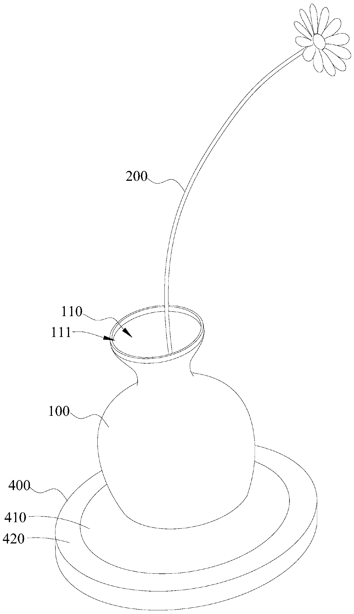
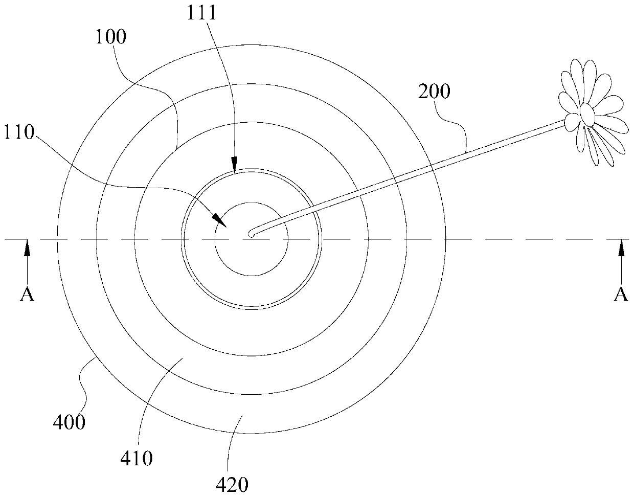
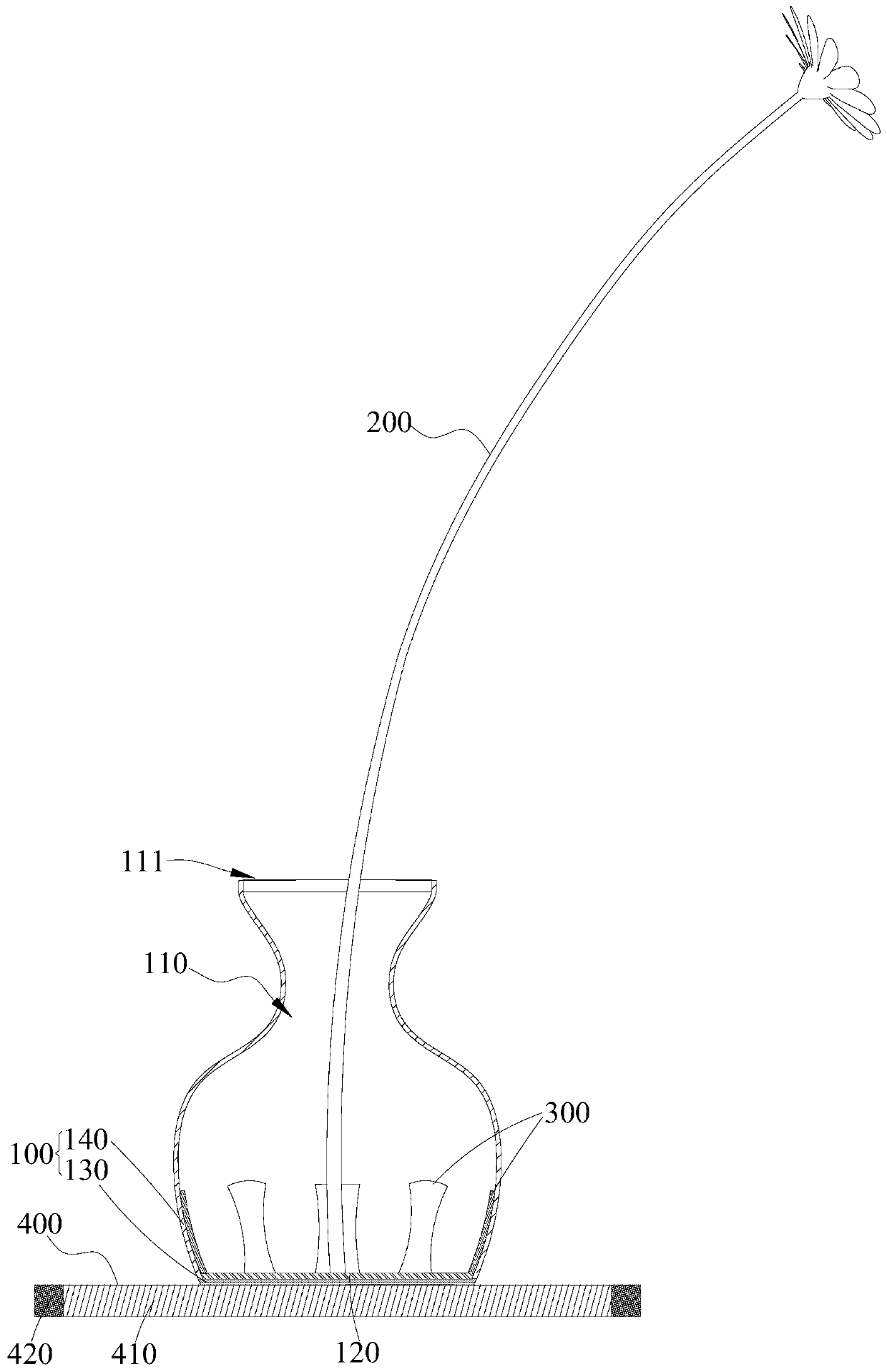
The invention is applicable to the technical field of communication, and provides an antenna. The antenna comprises a container, at least one first radiation part and a feed part; the container is provided with an accommodating cavity with an opening, and the bottom in the accommodating cavity is provided with a first feed part; the first radiation part is inserted into the accommodating cavity from the opening and is electrically connected with the first feed part; the feeding part is arranged outside the container; the second feed part is electrically connected with the first feed part; a client can insert different first radiation parts into the accommodating cavity according to requirements or adjust the number of the first radiation parts to adjust the radiation frequency covered by the antenna, so that the frequency band requirements of different clients on the antenna are met, and the antenna is simple in structure and low in cost and meets the purchasing power of most of consumers.

Description

technical field [0001] The invention relates to the technical field of communications, in particular to an antenna. Background technique [0002] Indoor antenna is a kind of antenna, which is mainly used for indoor signal coverage. According to different requirements, the frequency band covered by the antenna can be designed. Different users have different requirements for the frequency band of the antenna. Therefore, in order to meet the needs of customers, the manufacturer can customize the antenna according to the requirements of different customers for the frequency band, but this will greatly increase the production cost of the antenna. Contents of the invention [0003] The object of the present invention is to provide an antenna, aiming at solving the technical problem of high cost of customizing antennas according to different customers' requirements on frequency bands. [0004] The present invention is achieved like this, an antenna, comprising: [0005] A conta...

Claims


Application Information

Patent Timeline
Patent Type & Authority Applications(China)
IPC IPC(8): H01Q1/36H01Q1/50H01Q1/12H01Q1/00
CPCH01Q1/12H01Q1/36H01Q1/44H01Q1/50
Inventor 杨瑞典孔爱华陆伟明
Owner SHENZHEN ANTOP TECH
Learn More