
Inverted-F antenna with double-branch, short-circuit structure

A dual-branch, antenna technology, applied in the direction of the antenna, resonant antenna, radiating element structure, etc., can solve the problems of narrow bandwidth, complex structure, and many meandering current paths, etc., to achieve increased bandwidth and good impedance matching. Effect

Inactive Publication Date: 2011-01-12
连展科技电子(昆山)有限公司
View PDF1 Cites 0 Cited by
  • Summary
  • Abstract
  • Description
  • Claims
  • Application Information

AI Technical Summary

Problems solved by technology

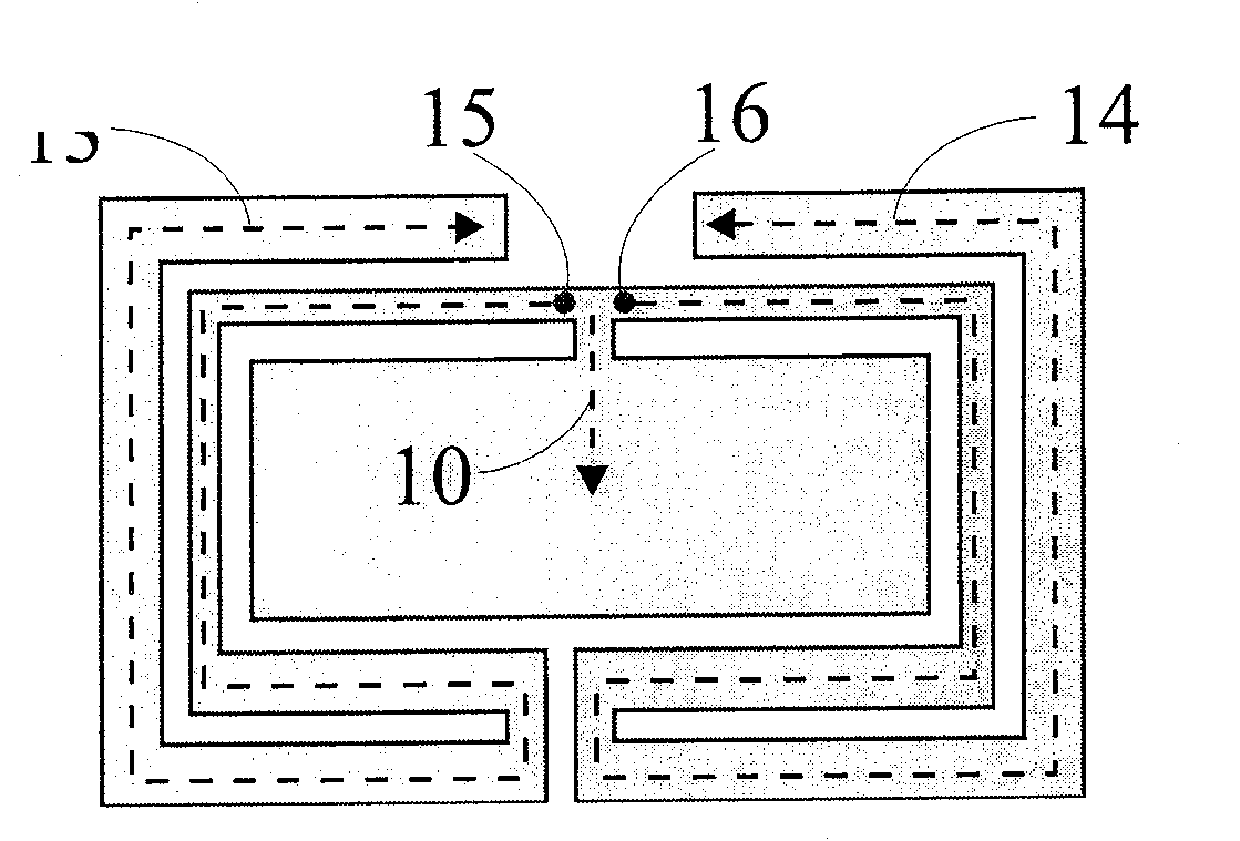
[0003] The built-in antennas currently used in mobile communication devices such as mobile phones, personal digital assistants (PDAs) and other products usually adopt an inverted-F antenna design, and the conventional inverted-F antenna design is such as US Patent No. 6,727,854 "inverted-F" Panel Antenna"( figure 1 ), which discloses a built-in antenna applied to mobile phones. The antenna mainly radiates the metal sheet part, which can be roughly divided into three current paths 10, 13, and 14 starting from the feed-in point 15 and the short-circuit point 16. The path excites different resonant frequencies to synthesize dual-frequency operation that meets the requirements of the GSM / DCS frequency band; this type of inverted-F antenna design usually only has a short-circuited metal sheet with a single branch, and its structure is relatively complex, and the current path is more winding , resulting in a narrow bandwidth that can only achieve dual-band operation, and it is difficult to adjust the characteristics of the antenna in practical applications

Method used


Image

  • Inverted-F antenna with double-branch, short-circuit structure
  • Inverted-F antenna with double-branch, short-circuit structure
  • Inverted-F antenna with double-branch, short-circuit structure

Examples


Embodiment 2

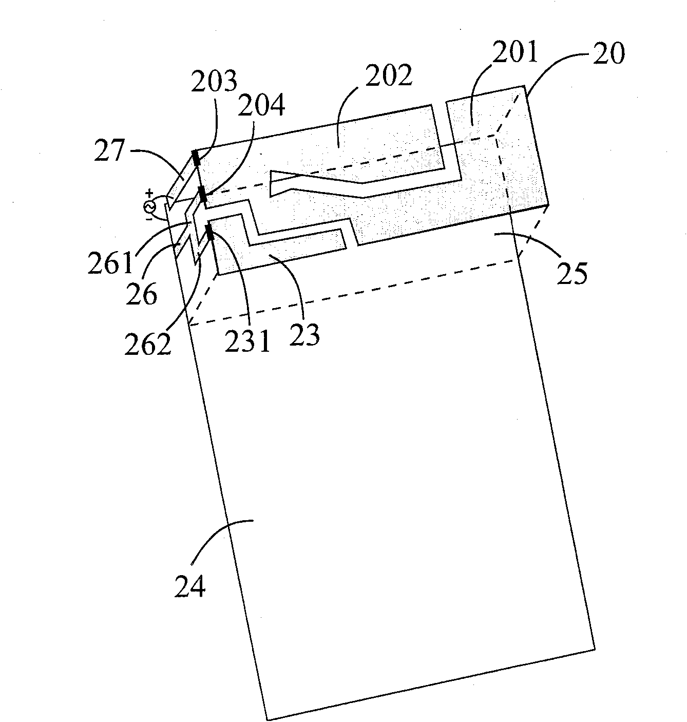
[0011] Such as figure 2 Shown is an embodiment 2 of the inverted-F antenna with a double-branch short-circuit structure of the present invention, which includes: a main radiation metal sheet 20, a secondary radiation metal sheet 23, a ground plane 24, and a dielectric substrate 25 , a double-branch short-circuit metal sheet 26 and a feed-in metal sheet 27; wherein, the main radiation metal sheet 20 includes a first sub-radiation metal sheet 201, a second sub-radiation metal sheet 202, a feed-in point 203 and a The first short-circuit point 204, wherein the feeding point 203 and the first short-circuit point 204 are located on the same edge of the main radiating metal sheet, and the first sub-radiating metal sheet 201 forms a longer current path for The first (low frequency) operation mode of the antenna is generated, and the second sub-radiating metal sheet 202 forms a shorter current path for generating the second (high frequency) operation mode of the antenna; the sub-radia...

Embodiment 4

[0013] Such as Figure 4 Shown is another embodiment 4 of the inverted-F antenna with a double-branch short-circuit structure of the present invention, which includes: a main radiating metal sheet 40, a secondary radiating metal sheet 43, a ground plane 44, and a dielectric substrate 45. A double-branch short-circuit metal sheet 46 and a feed-in metal sheet 47; wherein, the main radiation metal sheet 40 includes a first sub-radiation metal sheet 401, a second sub-radiation metal sheet 402, a feed-in point 403 and A first short-circuit point 404, wherein the feed-in point 403 and the first short-circuit point 404 are located on different edges of the main radiating metal sheet 40, and the first sub-radiating metal sheet 401 forms a longer current path for To generate the first (low frequency) operation mode of the antenna, the second sub-radiating metal sheet 402 forms a shorter current path for generating the second (high frequency) operation mode of the antenna; 43 can gener...

Embodiment 5

[0014] Such as Figure 5Shown is yet another embodiment 5 of the inverted-F antenna with a double-branch short-circuit structure of the present invention, which includes: a main radiation metal sheet 50, a secondary radiation metal sheet 53, a ground plane 54, and a dielectric substrate 55. A double-branch short-circuit metal sheet 56 and a feed-in metal sheet 57; wherein, the main radiation metal sheet 50 includes a first sub-radiation metal sheet 501, a second sub-radiation metal sheet 502, a feed-in point 503 and A first short-circuit point 504, wherein the feeding point 503 is located on an edge of the main radiating metal sheet 50, and the first short-circuit point 504 is located inside the main radiating metal sheet 50, and the first sub-radiating metal sheet The sheet 501 forms a longer current path for generating the first (low frequency) mode of operation of the antenna, and the second sub-radiating metal sheet 502 forms a shorter current path for generating the secon...


PUM


Abstract

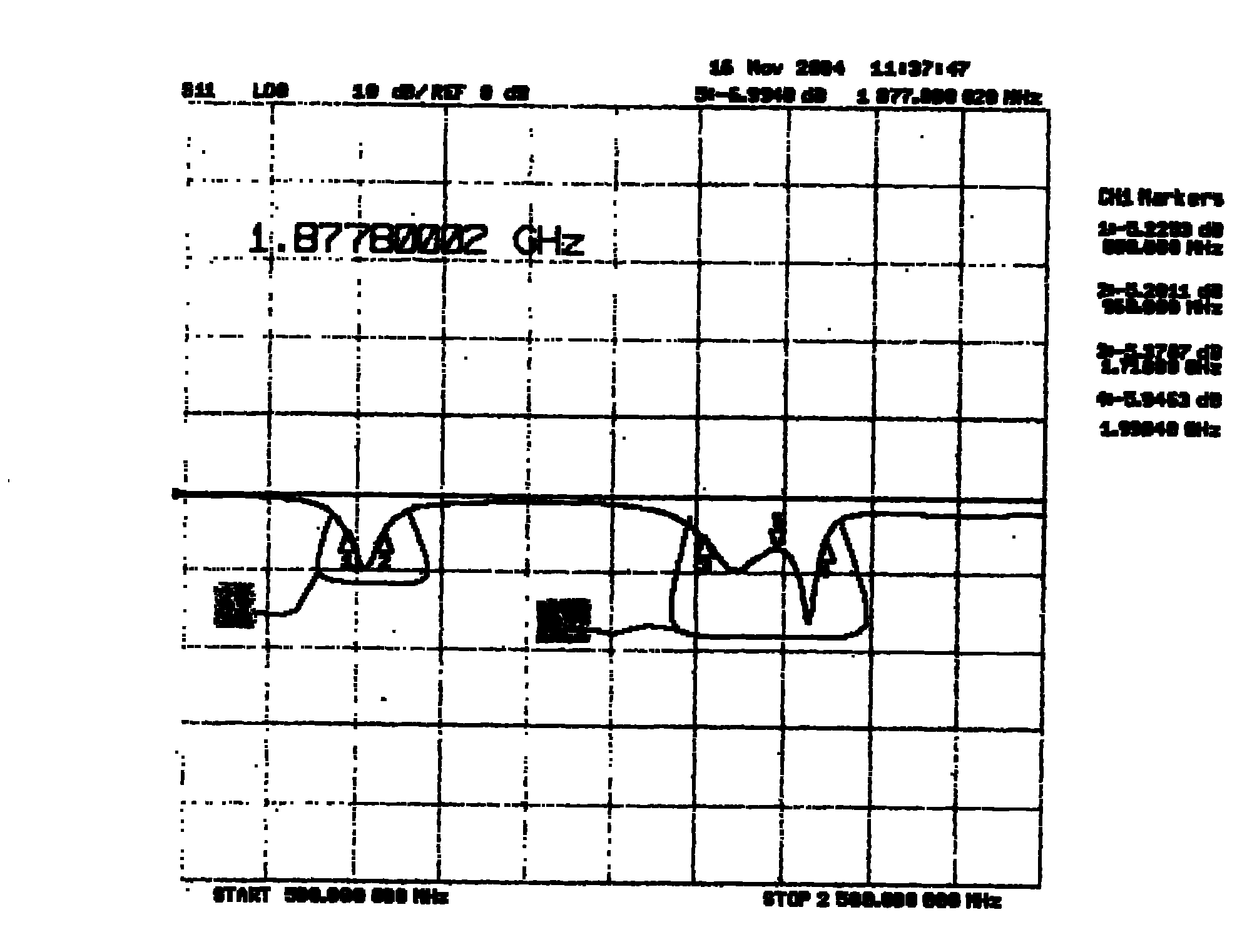
This invention relates to a kind of inverse F type antenna with double braches short circuit structure. The antenna concludes: a main radiating metal sheet, a accessory radiating metal sheet, a ground connected face, a dielectric base, a double branches short circuit metal sheet and a feeding metal sheet. The main radiating metal sheet concludes a first sub-radiating metal sheet, a secondary sub-radiating metal sheet, a feeding point and a first short circuit point. The first sub-radiating metal sheet forms a long electric current path, which generates first (low-frequency) operation mode of the antenna. The secondary sub-radiating metal sheet forms a short electric current path, which generates second (high-frequency) operation mode of the antenna. The accessory radiating metal sheet is used for increasing the operating frequency band of second (high-frequency) operation mode of the antenna. The accessory radiating metal sheet concludes a secondary short circuit point. One end of thedouble branches short circuit metal sheet connects to the ground connected face, the other end has a double branches structure which connects to the first short circuit point of main radiating sheet and the secondary short circuit point of accessory radiating metal sheet respectively. One end connects to the feeding point of main radiating metal sheet, the other end to system signal source so as to transferring signal. This invention has multi-frequency ability. Its frequency band is defined that it can reach 90MHz and 300MHz respectively at low-frequency and high-frequency range. It can easily cover GSM 900 / 1800 and DCS three-frequency frequency band of mobile communication.

Description

technical field [0001] The invention relates to an inverted-F antenna (inverted-F antenna), especially an antenna applied to wireless communication products. Background technique [0002] With the rapid development of wireless communication in recent years, the performance requirements of antennas have also gradually increased. In addition to the reduction in size, the antenna characteristics must also have the characteristics of multi-band or large bandwidth in order to meet market demand. In terms of appearance and practical convenience, it is gradually moving towards the miniaturized built-in antenna design. In order to achieve the reduction in size and maintain the characteristics of multi-band or wide-band antenna characteristics, the built-in antenna is usually made The design tends to be complicated. Therefore, how to use effective antenna parameters to meet the specifications required by the product in a limited environment and space has become an important guidelin...

Claims


Application Information

Patent Timeline
Patent Type & Authority Patents(China)
IPC IPC(8): H01Q1/36H01Q1/38H01Q9/28H01Q13/00
Inventor 陈逸仙邱宗文张秉宸萧富仁
Owner 连展科技电子(昆山)有限公司
Learn More