Magnet structure, method for manufacturing magnet structure, and method for manufacturing rotating electrical machine

A manufacturing method and structure technology, which can be used in the manufacture of motor generators, stator/rotor bodies, magnetic objects, etc., and can solve the problems of difficult magnetization and large magnetization deviation of magnets.

Inactive Publication Date: 2020-02-21
TDK CORPARATION
View PDF1 Cites 0 Cited by
  • Summary
  • Abstract
  • Description
  • Claims
  • Application Information

AI Technical Summary

Problems solved by technology

[0006] However, in the case of magnetizing a large magnet structure, it is difficult to achieve suffici

Method used


Image

  • Magnet structure, method for manufacturing magnet structure, and method for manufacturing rotating electrical machine
  • Magnet structure, method for manufacturing magnet structure, and method for manufacturing rotating electrical machine
  • Magnet structure, method for manufacturing magnet structure, and method for manufacturing rotating electrical machine

Examples


Embodiment Construction

[0030] Various embodiments and examples will be described below with reference to the drawings. However, the same or corresponding parts are denoted by the same symbols in the respective drawings, and repeated descriptions will be omitted.

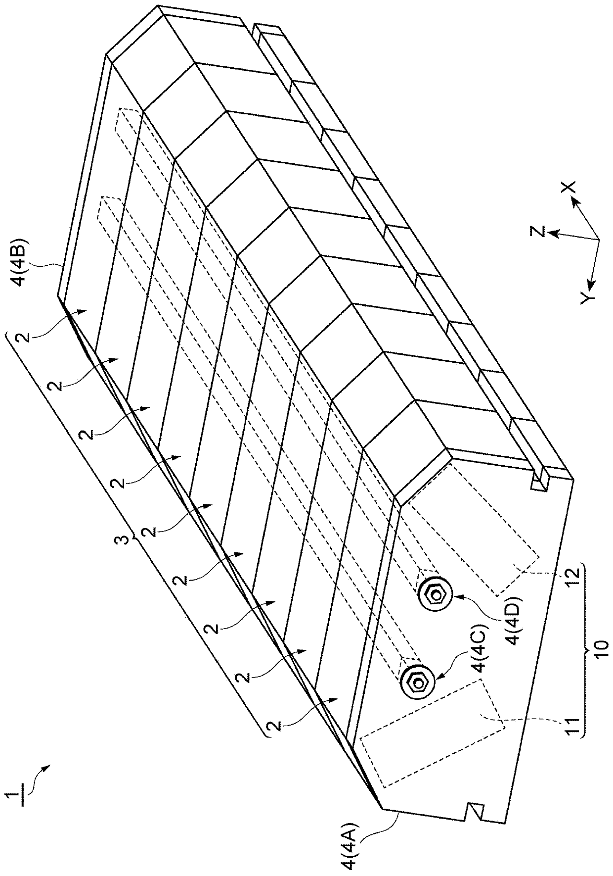
[0031] Such as figure 1 As shown, the magnet structure 1 according to the embodiment includes a laminated body 3 in which a plurality of magnet structural members 2 are stacked. In this embodiment, the laminated body 3 has nine magnet structural parts 2, and the nine magnet structural parts 2 are along one direction ( figure 1 in the X direction) arrangement.

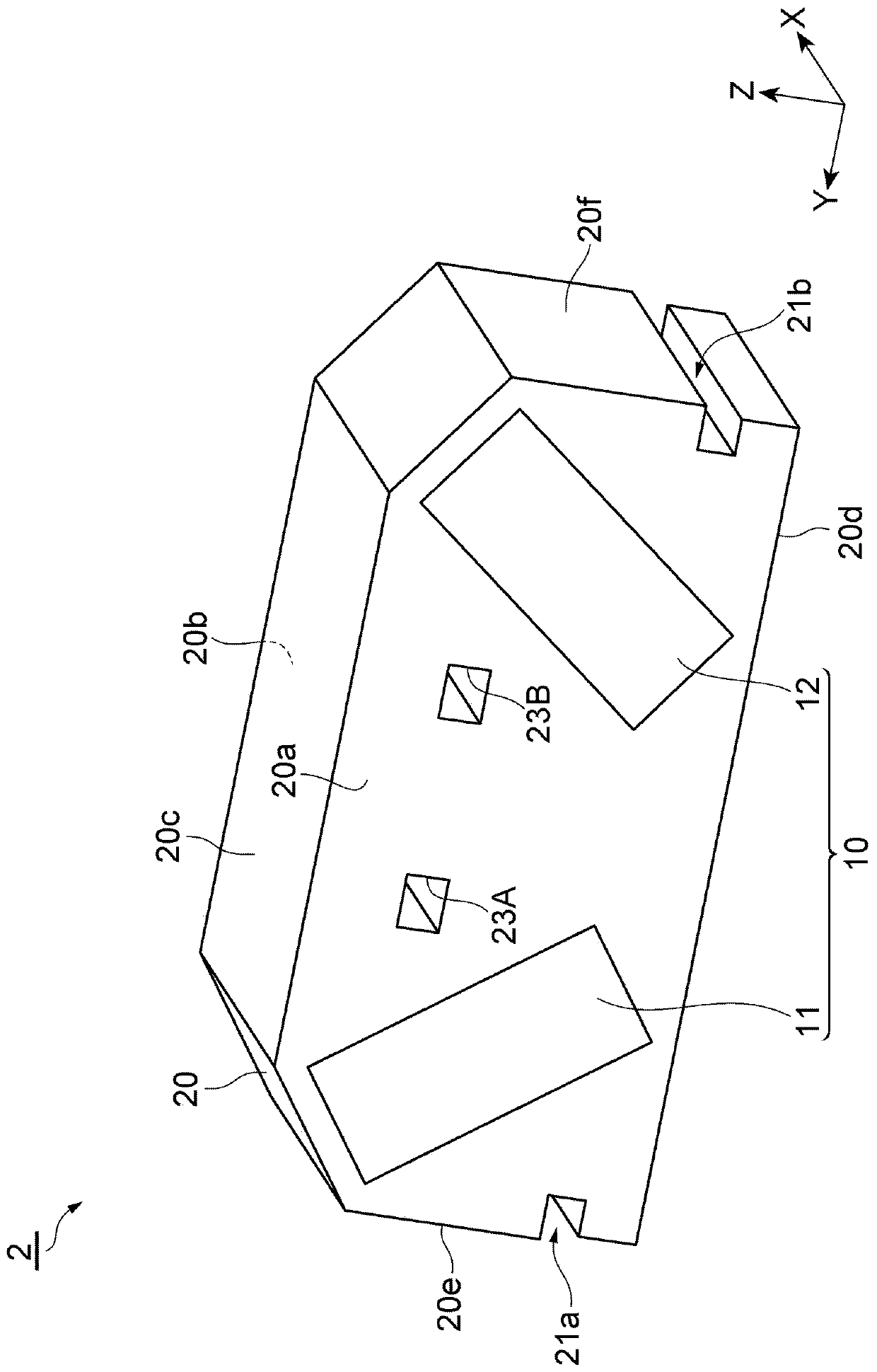
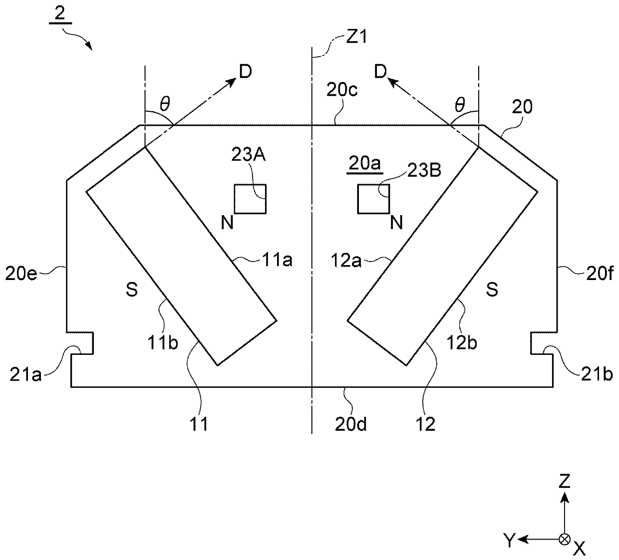
[0032] Each magnet construction part 2 such as figure 2 As shown, a pair of magnets 10 and a holder 20 are provided.

[0033] The holder 20 is made of, for example, a magnetic material such as laminated electrical steel sheets. The holder 20 has a substantially rectangular parallelepiped outer shape. The holding body 20 has a first end surface 20 a and a second end surface 20...


PUM


Abstract

The invention provides a magnet structure which is easy to magnetize, a method for manufacturing the magnet structure, and a method for manufacturing a rotating electrical machine. In the magnet structure and the manufacturing method thereof according to the present disclosure, the magnet structure has a structure provided with a plurality of magnet structure members, and the plurality of stackedmagnet structure members are restrained by a restraint. In this magnet structure, a plurality of magnet structure members can be magnetized by a magnetization step. In the magnetization step, the object to be magnetized is a magnet structure member that is smaller than the entire magnet structure. Therefore, a magnetizing device that is smaller than a magnetizing device that magnetizes the entiremagnet structure can be used, and the magnetization of the magnet structure can be performed more easily.

Description

technical field [0001] The present disclosure relates to a magnet structure, a method of manufacturing the magnet structure, and a method of manufacturing a rotating electrical machine. Background technique [0002] JP 2013-520149 (Patent Document 1) discloses a magnet structure used in a wind power generator. In recent years, with the increase in size of wind power generators, the demand for magnet structures having high magnetic force has increased, and the magnet structures themselves have also been increased in size along with the increase in size of magnets included in the magnet structures. [0003] As a method of assembling the above-mentioned magnet structure, there is a method of assembling the magnet structure after magnetizing the magnet, and a method of assembling the magnet structure with an unmagnetized magnet and then magnetizing each magnet structure. [0004] In the former method, especially in the case of a large magnet structure, it is difficult to safely...

Claims


Application Information

Patent Timeline
IPC IPC(8): H02K15/03H01F13/00
CPCH01F13/003H02K15/03
Inventor 儿岛伸生川岛伸也
Owner TDK CORPARATION
Why Eureka
Try Eureka