A magnetic elastic cable force sensor and a steel cable force measuring system

A cable force sensor, steel cable technology, applied in the direction of measuring force, measuring device, instrument, etc., can solve the problems that the coil is difficult to ensure consistency, the workload is large, and the technical requirements of workers are high.

Active Publication Date: 2019-06-25
NANCHANG HANGKONG UNIVERSITY
View PDF7 Cites 0 Cited by
  • Summary
  • Abstract
  • Description
  • Claims
  • Application Information

AI Technical Summary

Problems solved by technology

For the steel cables of the built bridges, if the sleeve structure is adopted, it can only be wound on site, but it is difficult to ensure the consistency of the coils wound in this way, and it is difficult to carry out accurate calibration, resulting in large measurement results At the same time, the on-site winding workload is large and the operation is inconvenient, which not only increases the difficulty of the operation, but also requires high technical requirements for the workers.
[0006] The magnetic elastic cable force sensor with a bypass structure uses a U-shaped magnetic yoke. The excitation coil does not need to be wound on site. The magnetic flux passes through the magnetic yoke and enters the steel cable, which can realize the magnetization of the steel cable. However, the detection coil of this sensor still needs to be wound. on steel cables

Method used


Image

  • A magnetic elastic cable force sensor and a steel cable force measuring system
  • A magnetic elastic cable force sensor and a steel cable force measuring system
  • A magnetic elastic cable force sensor and a steel cable force measuring system

Examples


Embodiment Construction

[0037] The following will clearly and completely describe the technical solutions in the embodiments of the present invention with reference to the accompanying drawings in the embodiments of the present invention. Obviously, the described embodiments are only some, not all, embodiments of the present invention. Based on the embodiments of the present invention, all other embodiments obtained by persons of ordinary skill in the art without making creative efforts belong to the protection scope of the present invention.

[0038] The object of the present invention is to provide a magnetic elastic cable force sensor and a steel cable force measuring system.

[0039] In order to make the above objects, features and advantages of the present invention more comprehensible, the present invention will be further described in detail below in conjunction with the accompanying drawings and specific embodiments.

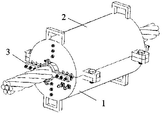
[0040] figure 1 It is a schematic diagram of the structure when the cross...


PUM

PropertyMeasurementUnit
thicknessaaaaaaaaaa

Abstract

The invention discloses a magnetic elastic cable force sensor and a steel cable force measuring system. The sensor includes: a fixed bracket and a sensor module; the sensor module is composed of two parts; when the two parts constitute the sensor module, the sensor module is covered on the outside of the steel cable; the sensor module includes a shell, Copper sheet coil and detection coil; the inside of the shell is a hollow cavity, the copper sheet coil and the detection coil are installed in the hollow cavity; the detection coil surrounds the outside of the steel cable, and the copper A sheet coil surrounds the outside of the detection coil; the fixing bracket is installed on the steel cable, located on both sides of the sensor module, and fixes the sensor module on the steel cable. The magnetic elastic cable force sensor and the steel cable force measuring system disclosed by the invention have the advantages of simple and convenient installation and are applicable to steel cables of various shapes while ensuring high-precision measurement.

Description

technical field [0001] The invention relates to the field of non-destructive testing, in particular to a magnetic elastic cable force sensor and a steel cable force measuring system. Background technique [0002] Due to the outstanding advantages of high flexibility, high tensile strength, and long load transmission distance, steel cables have been widely used in fields such as long-span bridges, large-scale building structures, and traction machinery, including cable-stayed cables, passenger ropeways, steel wire ropes for elevators, and All kinds of lifting equipment slings and other forms. During the use of the steel cable, damage will accumulate due to the influence of atmospheric environment corrosion, mechanical friction or fatigue damage; at the same time, due to the uncertainty of the load, the steel cable will inevitably suffer various damages, resulting in the actual load of the steel cable. The capacity is reduced, so that the steel cable may suddenly break due to...

Claims


Application Information

Patent Timeline
Patent Type & Authority Patents(China)
IPC IPC(8): G01L1/12
CPCG01L1/127
Inventor 宋凯徐聪王振杨琳瑜王冲蒋诗超
Owner NANCHANG HANGKONG UNIVERSITY
Why Eureka
Try Eureka