A Mathematical Probability Demonstration Model
A probability and model technology, applied in teaching models, instruments, educational appliances, etc., can solve problems such as lack of support, and achieve the effect of fast recognition
- Summary
- Abstract
- Description
- Claims
- Application Information
AI Technical Summary
Problems solved by technology
Method used
Image
Examples
Embodiment 1
[0027] This embodiment provides a mathematical probability demonstration model, and implements the present invention through basic necessary technical features to solve the problems raised in the technical background section of this application document.
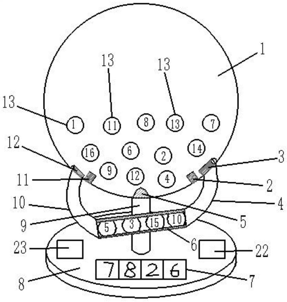
[0028] Specifically, such as figure 1 As shown, the embodiment of the present invention provides a mathematical probability demonstration model, including a base 8, a pillar 9 is fixed on the base 8, a hollow shell 1 is fixed on the top of the pillar 9, and a plurality of surfaces are arranged in the hollow shell 1. The sphere 13 marked with numbers, the hollow shell 1 is provided with a rotating fan 5 for making the sphere 15 move irregularly, and the left and right sides of the lower end of the hollow shell 1 are respectively connected with the ball inlet pipe 4 and the ball outlet pipe 10. The free end of the ball-in tube 4 and the free end of the ball-out tube 10 are connected through the display tube 6, and the inner an...
Embodiment 2
[0032] This example is based on Example 1 and optimizes the implementation in Example 1, so that this example is more stable and has better performance during operation, but it is not limited to the one described in this example implementation.
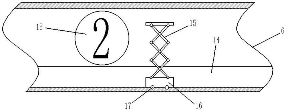
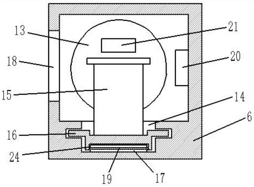
[0033] Specifically, such as Figure 2-3 As shown, the pushing mechanism includes chutes 14 respectively provided at the bottom of the digital display tube 6 and the ball outlet tube 10 along the length direction, and the chute 14 of the digital display tube 6 is connected with the chute 14 of the ball outlet tube 10 And the surface of the joint is smooth and continuous. The slide groove 14 is slidingly fitted with a slide block 16, and a lifter 15 is arranged on the slide block 16. When the lifter 15 is in the lowest state, the upper surface of the lifter 15 does not exceed the The notch of the chute 14, when the lifter 15 is in the highest state, the upper surface of the lifter 15 does not contact the display tube 6 of the chute 14...
Embodiment 3
[0039] This example is based on Example 1 and optimizes the implementation in Example 1, so that this example is more stable and has better performance during operation, but it is not limited to the one described in this example implementation.
[0040] Specifically, the sphere 13 is provided with an RFID electronic tag 21 with a working frequency band of 13.56M. The RFID electronic tag 21 is used to store a number consistent with the number marked on the surface of the sphere 13. The identifier is used to identify The RFID reader 20 of the RFID electronic tag 21.
[0041] When identifying the numbers on the surface of the sphere 13, use the RFID electronic tag 21 with a working frequency band of 13.56M to be installed inside the sphere 13, and use the corresponding RFID reader 20 to identify the numbers. The numbers on the surface of the sphere 13 are more accurate, and at the same time, the recognition speed will be faster. Since the identification range of the 13.56M RFID...
PUM
 Abstract
Description
Claims
Application Information
 - R&D
- Intellectual Property
- Life Sciences
- Materials
- Tech Scout
- Unparalleled Data Quality
- Higher Quality Content
- 60% Fewer Hallucinations
Browse by: Latest US Patents, China's latest patents, Technical Efficacy Thesaurus, Application Domain, Technology Topic, Popular Technical Reports.
© 2025 PatSnap. All rights reserved.Legal|Privacy policy|Modern Slavery Act Transparency Statement|Sitemap|About US| Contact US: help@patsnap.com


