Liquid ejection device and multi-nozzle liquid ejection device

A nozzle type, nozzle technology, applied in the printing device, printing and other directions, can solve the problem of unstable ink ejection and so on

Active Publication Date: 2020-03-06
TOSHIBA TEC KK
View PDF7 Cites 1 Cited by
  • Summary
  • Abstract
  • Description
  • Claims
  • Application Information

AI Technical Summary

Problems solved by technology

However, when a plurality of actuators are driven at approximately the same timing, the ejection of ink so

Method used


Image

  • Liquid ejection device and multi-nozzle liquid ejection device
  • Liquid ejection device and multi-nozzle liquid ejection device
  • Liquid ejection device and multi-nozzle liquid ejection device

Examples


no. 1 approach

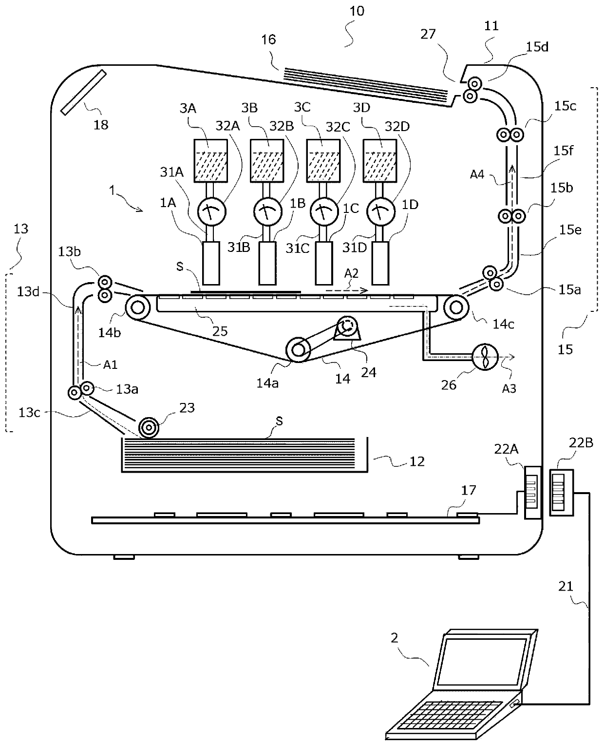
[0043] An inkjet printer 10 that prints an image on a recording medium will be described as an example of an image forming apparatus equipped with the liquid ejection device 1 according to the embodiment. figure 1 A schematic configuration of the inkjet printer 10 is shown. The inkjet printer 10 includes, for example, a box-shaped casing 11 as an outer package. Inside the casing 11, a cassette 12 for accommodating a sheet S as an example of a recording medium, an upstream transport path 13 for the sheet S, a conveyor belt 14 for transporting the sheet S taken out from the cassette 12, and a direction transport Inkjet heads 1A to 1D that eject ink droplets from the sheet S on the belt 14 , a downstream conveyance path 15 of the sheet S, a discharge tray 16 , and a control board 17 . An operation unit 18 as a user interface is provided on the upper side of the casing 11 .

[0044] The image data printed on the sheet S is generated by, for example, the computer 2 as an external...

no. 2 approach

[0123] Next, a liquid ejection device according to a second embodiment will be described. Figure 31 A longitudinal cross-sectional view of an inkjet head 101A as an example of a liquid ejection device is shown. The inkjet head 101A has the same configuration as the inkjet head 1A illustrated in the first embodiment except that the pressure chamber (individual pressure chamber) 41 is omitted and the nozzle plate 5 communicates directly with the common ink chamber 42 . Therefore, for Figure 4For the same configuration, the detailed description thereof will be omitted by assigning the same reference numerals.

[0124] Figure 31 The illustrated inkjet head 101A is also driven by generating and driving waveforms having different start timings for allocation of all channels. In this case as well, it is possible to realize a multi-nozzle type inkjet head capable of canceling out the crosstalk applied to channels of interest for the reasons described above.

[0125] That is, th...


PUM

PropertyMeasurementUnit
The inside diameter ofaaaaaaaaaa
Outer diameteraaaaaaaaaa
Diameteraaaaaaaaaa

Abstract

The invention provides a liquid ejection device and a multi-nozzle liquid ejection device that can suppress the crosstalk of inerference of motions of an actuator and performs stable liquid ejection.According to one embodiment, a liquid ejection device 1A includes a nozzle plate 5, an actuator 8, a liquid supply unit 2, a waveform generation circuit 301, a waveform allocation circuit 302, and a drive signal output circuit. A plurality of nozzles 51 for ejecting liquid is arranged in the nozzle plate. The actuator is provided in each of the nozzles. The waveform generation circuit generates plural kinds of drive waveforms with different generation start timings. The waveform allocation circuit can set the drive waveform among plural kinds of drive waveforms and the actuator of the nozzle to be allocated. The drive signal output circuit drives the actuator with the allocated drive waveform.

Description

technical field [0001] Embodiments of the present invention relate to a liquid ejection device and a multi-nozzle type liquid ejection device. Background technique [0002] There is known a liquid discharge device that supplies a predetermined amount of liquid to a predetermined position. The liquid ejection device is mounted on, for example, an inkjet printer, a 3D printer, a dispensing device, or the like. An inkjet printer ejects ink droplets from an inkjet head to form an image or the like on the surface of a recording medium. The 3D printer ejects the liquid droplets of the modeling material from the modeling material nozzle and solidifies them to form a three-dimensional modeling object. The dispensing device ejects liquid droplets of a sample and supplies a predetermined amount of liquid droplets of the sample to a plurality of containers or the like. [0003] A liquid ejection device including a plurality of nozzles that eject ink by driving actuators drives the p...

Claims


Application Information

Patent Timeline
IPC IPC(8): B41J2/14B41J29/38
CPCB41J2/14B41J29/38B41J2002/14459B41J2/04525B41J2/04573B41J2/04595B41J2/04588B41J2/04541B41J2/04581B41J2/03B41J2/04546
Inventor 仁田昇小野俊一原田苍太
Owner TOSHIBA TEC KK
Why Eureka
Try Eureka