

Inkjet device and inkjet method
An inkjet device and coating technology, applied in printing, typewriter and other directions, can solve the problems of ink droplets, unstable spraying of the coating head, etc., and achieve the effect of stable spraying
- Summary
- Abstract
- Description
- Claims
- Application Information
AI Technical Summary
Problems solved by technology
Method used
Image

Examples
Embodiment approach 1
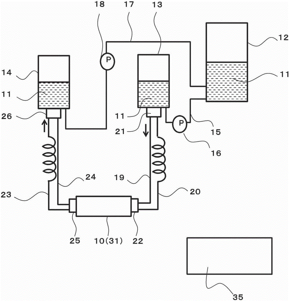
[0049] figure 1 It is a schematic diagram of the ink jet device according to Embodiment 1 of the present invention.
[0050] The entire inkjet device is covered with a UV light-blocking film and a metal cover so that the ink in each tank, pipe, and coating head under the action of UV light will not deteriorate. This example is for the case of using ink for UV light, and when not using ink for UV light, the above countermeasures are not essential.
[0051] In the inkjet device, a plurality of coating heads 10 arranged with a plurality of nozzles ejecting a predetermined amount of ink and the following three tanks are arranged: a storage tank 12 for storing ink 11; A supply tank 13 for the ink 11; and a recovery tank 14 for storing the ink 11 recovered from the coating head 10 in advance. In addition, there is a control unit 35 that controls each component. The control unit 35 has a processor and the like, and issues control instructions to each component unit. Wiring is omi...
Embodiment 1
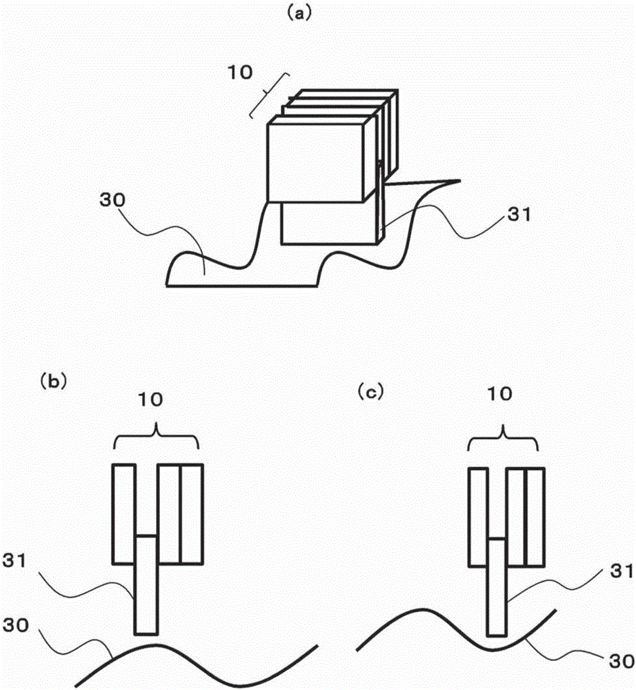
[0063] use figure 2 (a)~ figure 2 (c) Example 1 is described. figure 2 (a) is a perspective view of an applicator head. figure 2 (b)~ figure 2 (c) is a side view of the applicator head.
[0064] Such as figure 2 As shown in (a), an example is shown in which ink is ejected from the coating head 10 to form a predetermined pattern on the workpiece 30 with respect to the workpiece 30 having large unevenness.
[0065] At this time, the coating head 10 is comprised by 4 coating heads. The position of any one coating head 31 among the four coating heads is set at a lower position than the other coating heads 10 . Ink is ejected only from the coating head 31 set at the low position, and ink is not ejected from the other coating heads 10 . The workpiece 30 moves from the depth side of the coating head 31 to the near side, and ink is ejected from the coating head 31 to the workpiece to form a predetermined pattern. The workpiece 30 is fixed by a robot arm having a multi-ax...
Embodiment approach 2
[0095] Figure 4 A schematic diagram showing an inkjet device according to Embodiment 2 of the present invention. exist Figure 4 in, right with figure 1 The same components are denoted by the same symbols, and explanations thereof are omitted. Items not described are the same as those in Embodiment 1.
[0096] Embodiment 2 differs from Embodiment 1 in two supply pipes 40 and 41 connected from supply tank 13 to coating head 10 and two recovery pipes 42 and 43 for recovering ink 11 from coating head 10 .
[0097] The supply tank 13 and any coating head 10 are connected by two supply pipes 40 and 41 having the same length but having different pipe diameters (hereinafter referred to as different flow path areas). Either one of the two supply pipes 40 and 41 between the supply tank 13 and the coating head 10 is supplied via the switching valve 21 provided on the supply tank 13 and the switching valve 22 provided on the ink introduction side of the coating head 10 . The piping...
PUM
 Abstract
Description
Claims
Application Information