
Ignition system for smoke sprayers

An ignition system and fog machine technology, applied in the field of ignition systems, can solve the problems of easy flameout of negative pressure fuel, cumbersome ignition operation, and low ignition success rate, and achieve high ignition success rate, good atomization effect, and accurate coordination.

Active Publication Date: 2014-10-29
史文军 +1
View PDF9 Cites 2 Cited by
  • Summary
  • Abstract
  • Description
  • Claims
  • Application Information

AI Technical Summary

Problems solved by technology

[0005] The purpose of the present invention is to overcome the deficiencies of low ignition success rate, cumbersome ignition operation, and easy extinguishment after ignition by using negative pressure fuel in the existing fog machine, and provide a fog machine ignition system, adopting the technical scheme of the present invention, using the air pump as the fuel tank Pressurize and provide air for ignition, the fuel is stably ejected under positive pressure, fully mixed with air and then ignited by the spark plug, the mixed fuel is matched accurately with the spark plug, and the success rate of ignition is high; the ignition switch and fuel supply valve are integrated together , the ignition operation is convenient and quick; at the same time, after the ignition is successful, the vibrating diaphragm generates a stable pressure in the carburetor, on the one hand, it provides the air for fuel combustion, and on the other hand, it provides a stable positive pressure for the fuel tank, so that the fuel can be ejected stably , to achieve uninterrupted and stable work of the fog machine

Method used


Image

  • Ignition system for smoke sprayers
  • Ignition system for smoke sprayers

Examples


Embodiment

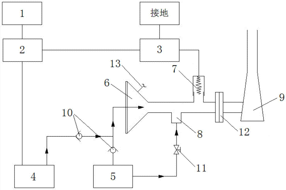
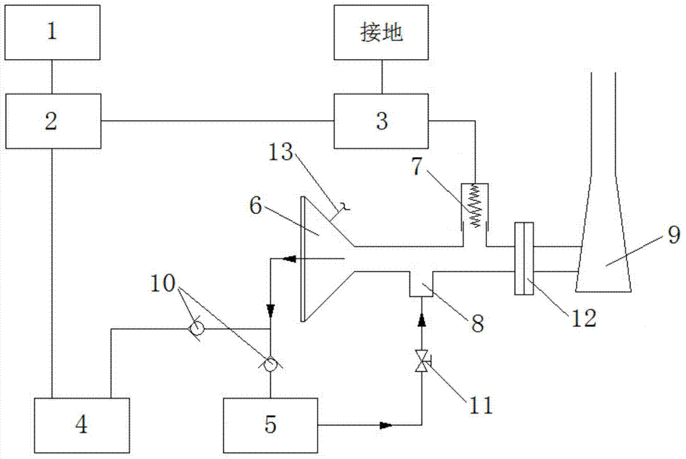
[0027] combine figure 1 with figure 2 , a kind of fog machine ignition system of the present embodiment, comprises power supply 1, ignition switch 2, igniter 3, air pump 4, fuel tank 5, carburetor 6, spark plug 7, fuel injection nozzle 8 and combustion chamber 9, igniter 3 and the air pump 4 are electrically connected to the power supply 1 through the ignition switch 2, and the ignition switch 2 controls the start and stop of the igniter 3 and the air pump 4 at the same time, which reduces the trouble of step-by-step operation, and is beneficial to the mutual cooperation of the ignition of the spark plug 7 and the mixing of fuel. Improve the ignition success rate; the igniter 3 is electrically connected to the spark plug 7, and the igniter 3 needs to be grounded at the same time to ensure that the smoke machine can be ignited normally; the air pump 4 is respectively connected to the fuel tank 5 and the carburetor 6 through the gas pipeline. It consists of two branches separa...


PUM


Abstract

The invention discloses an ignition system for smoke sprayers and belongs to the technical field of the smoke sprayers. The ignition system comprises a power supply, an ignition switch, an igniter, an oil tank, a carburetor, a sparking plug, an oil spray nozzle, a combustion chamber and an air pump, wherein the igniter and the air pump are electrically connected with the power supply respectively through the ignition switch, the igniter is electrically connected with the sparking plug, the air pump is respectively connected with the oil tank and the carburetor through air pipes, and check valves are respectively arranged on main paths of the air pipes and branch paths connected with the oil tank. The oil tank is connected with the oil spray nozzle through an oil supply pipe, and an oil supply valve is arranged on the oil supply pipe. The carburetor is connected with the combustion chamber, and the sparking plug and the oil spray nozzle are arranged on a connection pipe between the carburetor and the combustion chamber. By means of the air pump, pressurization of the oil tank is achieved, and air required by ignition is provided. Fuel oil is sprayed out stably under action of positive pressure, mixed fuel oil and the sparking plug are matched accurately, the success rate of ignition is high, and ignition operation is convenient and efficient. Meanwhile, continuous and stable operation of the smoke sprayers is achieved.

Description

technical field [0001] The present invention relates to an ignition system, and more particularly, to an ignition system for a smoke machine. Background technique [0002] The fog machine is widely used in the prevention and control of agricultural diseases and insect pests. Its medicine is fully atomized at night, and the particle size of the medicine mist is small. The medicine mist can diffuse in the operation area for a long time, and the insecticidal and sterilizing effect is good. What is widely used in the existing market is a portable pulse type fog machine, which usually consists of a pulse jet engine and a drug supply system. The pulse jet engine is composed of a combustion chamber, a nozzle, a starting system, a fuel supply system, and an ignition system; The drug supply system consists of a drug box, a drug switch, a drug outlet, and pipelines. This type of fog machine uses the high-temperature, pulse-type high-speed airflow ejected by the pulse jet engine to in...

Claims


Application Information

Patent Timeline
Patent Type & Authority Applications(China)
IPC IPC(8): A01M7/00
Inventor 史文军林仲荣
Owner 史文军
Learn More