Thin-type side-in and straight-out heat dissipation fan

A heat dissipation fan and side entry technology, which is applied to parts of pumping devices for elastic fluids, non-variable pumps, machines/engines, etc., can solve the problem that the fan cannot be used, the air inlet condition is unfavorable, and the fan can only be used horizontally Placement and other issues to achieve the effect of improving air intake conditions, good air intake conditions, and improving heat dissipation efficiency

Pending Publication Date: 2020-03-06
太仓市华盈电子材料有限公司
View PDF0 Cites 0 Cited by
  • Summary
  • Abstract
  • Description
  • Claims
  • Application Information

AI Technical Summary

Problems solved by technology

[0002] At present, cooling fans are divided into axial flow type and centrifugal type. The axial flow air inlet mode is axially in and axially out. When the axial flow cooling fan is applied to various products, it must be assembled above the heat source. The axial size is relatively large, which is limited by the thickness of the cooling system. , this kind of fan cannot be used; the centrifugal air intake method is up and down, and the air is blown out sideways. Due to the thickness limit of the cooling system, the fan can only be placed horizontally. Because the upper and lower sides need to enter the air, the air inlet is opened on the base of the cooling system, and the equipment is in use. During the process of placing objects on the surface, the air inlet will be largely covered, and the air inlet conditions are unfavorable, which cannot achieve a good heat dissipation effect; in view of these defects, it is necessary for us to design a thin side-in and straight-out cooling fan

Method used


Image

  • Thin-type side-in and straight-out heat dissipation fan
  • Thin-type side-in and straight-out heat dissipation fan
  • Thin-type side-in and straight-out heat dissipation fan

Examples


Embodiment Construction

[0016] The technical solutions of the present invention will be clearly and completely described below in conjunction with the embodiments. Apparently, the described embodiments are only some of the embodiments of the present invention, not all of them. Based on the embodiments of the present invention, all other embodiments obtained by persons of ordinary skill in the art without creative efforts fall within the protection scope of the present invention.

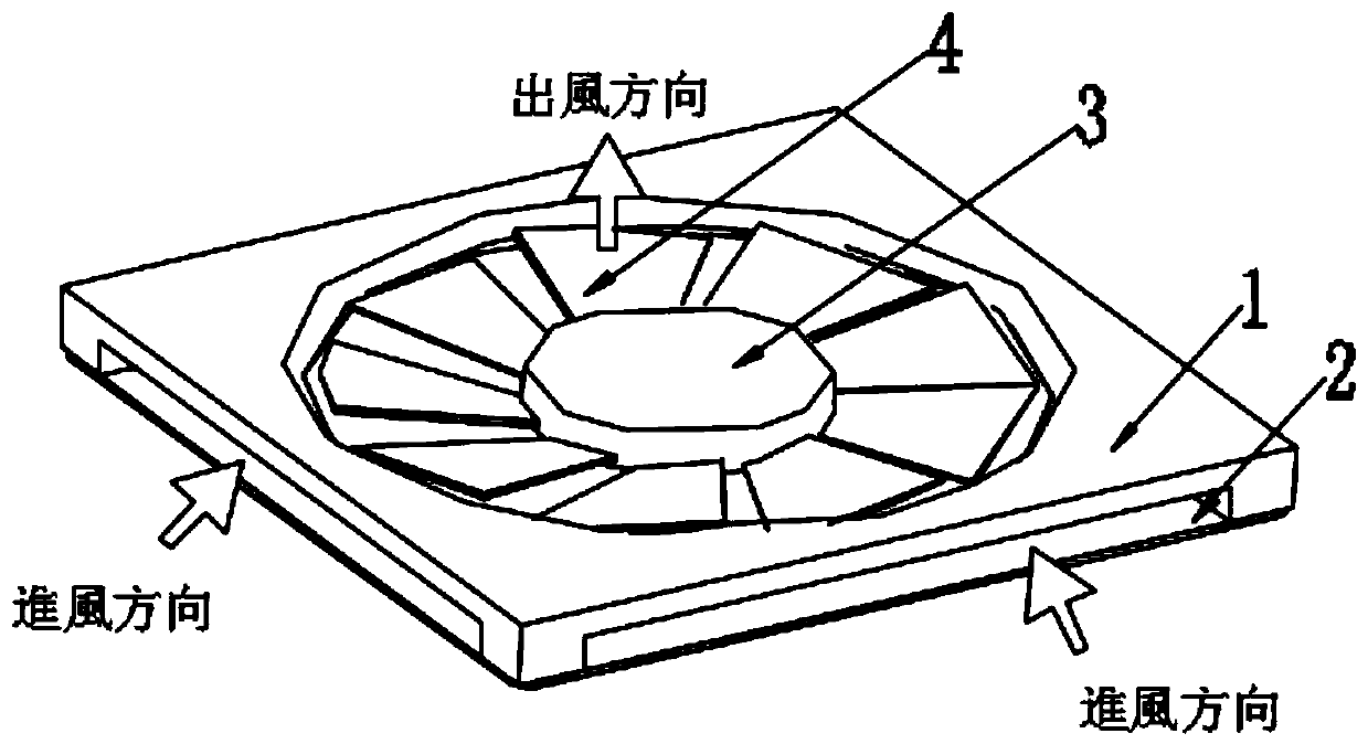
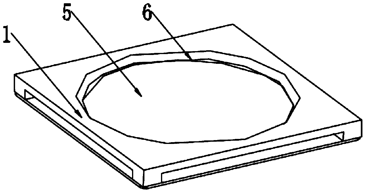
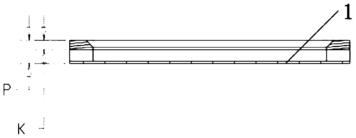
[0017] Such as Figure 1-6 As shown, the thin-type side-entry straight-out cooling fan includes a frame body 1, an air inlet 2, a rotating shaft 3, blades 4, a rotating groove 5, and a flow guide groove 6. The frame body 1 is a hollow structure, and the top center of the frame body 1 There is a rotating slot 5, and the top edge of the rotating slot 5 is provided with a diversion slot 6, and the four sides of the frame body 1 are provided with an air inlet 2, and the air inlet 2 and the rotating slot 5 are connected with the...


PUM


Abstract

The invention discloses a thin-type side-in and straight-out heat dissipation fan. The heat dissipation fan comprises a frame body, air inlets, a rotating shaft, blades, a rotating groove and a flow guiding groove; the frame body is of a hollow structure, the rotating groove is formed in the center position of the top of the frame body, the flow guiding groove is formed in the edge of the top of the rotating groove, the air inlets are formed in the four side faces of the frame body, each air inlet and the rotating groove communicate with the inner cavity of the frame body, the plurality of blades are uniformly arranged on the outer side of the rotating shaft, the bottom end of the rotating shaft is rotationally connected with the center of the inner wall of the bottom of the frame body, and the rotating shaft and the blades are located in the rotating groove; and the flow guiding groove is in an open shape from bottom to top. According to the heat dissipation fan, the heat dissipationfan is light and thin, the air inlet condition is improved, a novel air inlet mode is developed, and the heat dissipation efficiency of the fan is improved.

Description

technical field [0001] The invention relates to the technical field of cooling fans, in particular to a thin side-entry and straight-out cooling fan. Background technique [0002] At present, cooling fans are divided into axial flow type and centrifugal type. The axial flow air inlet mode is axially in and axially out. When the axial flow cooling fan is applied to various products, it must be assembled above the heat source. The axial size is relatively large, which is limited by the thickness of the cooling system. , this kind of fan cannot be used; the centrifugal air intake method is up and down, and the air is blown out sideways. Due to the thickness limit of the cooling system, the fan can only be placed horizontally. Because the upper and lower sides need to enter the air, the air inlet is opened on the base of the cooling system, and the equipment is in use. During the process of placing objects on the surface, the air inlet will be largely covered, and the air inlet ...

Claims


Application Information

Patent Timeline
Patent Type & Authority Applications(China)
IPC IPC(8): F04D29/42F04D29/28
CPCF04D29/281F04D29/4226
Inventor 范斌朱坤林连凯赖进龙
Owner 太仓市华盈电子材料有限公司
Why Eureka
Try Eureka