Rod system combination unloading system of circumferentially-expandable structure

A rod system and suspension rod technology, applied in the mechanical field, can solve the problems of interference, high manufacturing cost, inability to meet the deployable structure, etc., and achieve the effect of eliminating influence and avoiding interference.

Active Publication Date: 2020-03-10
SHANGHAI AEROSPACE SYST ENG INST
View PDF8 Cites 2 Cited by
  • Summary
  • Abstract
  • Description
  • Claims
  • Application Information

AI Technical Summary

Problems solved by technology

[0007] (1) Large friction and expensive manufacturing cost
The guide rail unloading system and the hoisting system bring a certain amount of resistance to the deployment of the deployable structure due to the many contact and sliding parts, and the factors affecting the deployment of the structure are judged by interference
[0008] (2) Poor stability
The balloon suspension unloading system has the disadvantages of instability, limited space, and many interference factors
[0009] (3) Unable to meet the needs of deployable structures with complex motion trajectories
The current unloading system can only meet the simple motion trajectory, such as the linear motion trajectory of the guide rail unloading system; it cannot satisfy the expandable structure with complex motion trajectory, such as the complex motion of the large flexible structure
[0010] (4) Not suitable for large-scale, high-precision deployable structures

Method used


Image

  • Rod system combination unloading system of circumferentially-expandable structure
  • Rod system combination unloading system of circumferentially-expandable structure
  • Rod system combination unloading system of circumferentially-expandable structure

Examples


Embodiment Construction

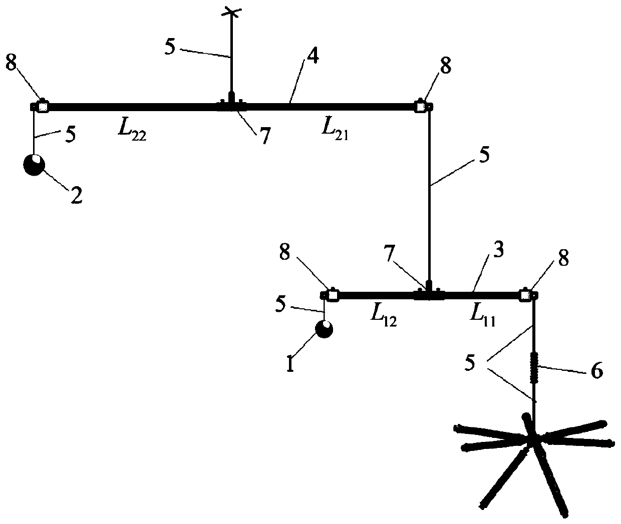
[0022] The present invention will be further described below in conjunction with specific embodiments and accompanying drawings. Marks in the figure: 1-lower counterweight; 2-upper counterweight; 3-lower lightweight suspension rod; 4-upper lightweight suspension rod; 5-rope; 6-light soft spring; 7-T-shaped sleeve; 8-Telescopic adjustment sleeve.

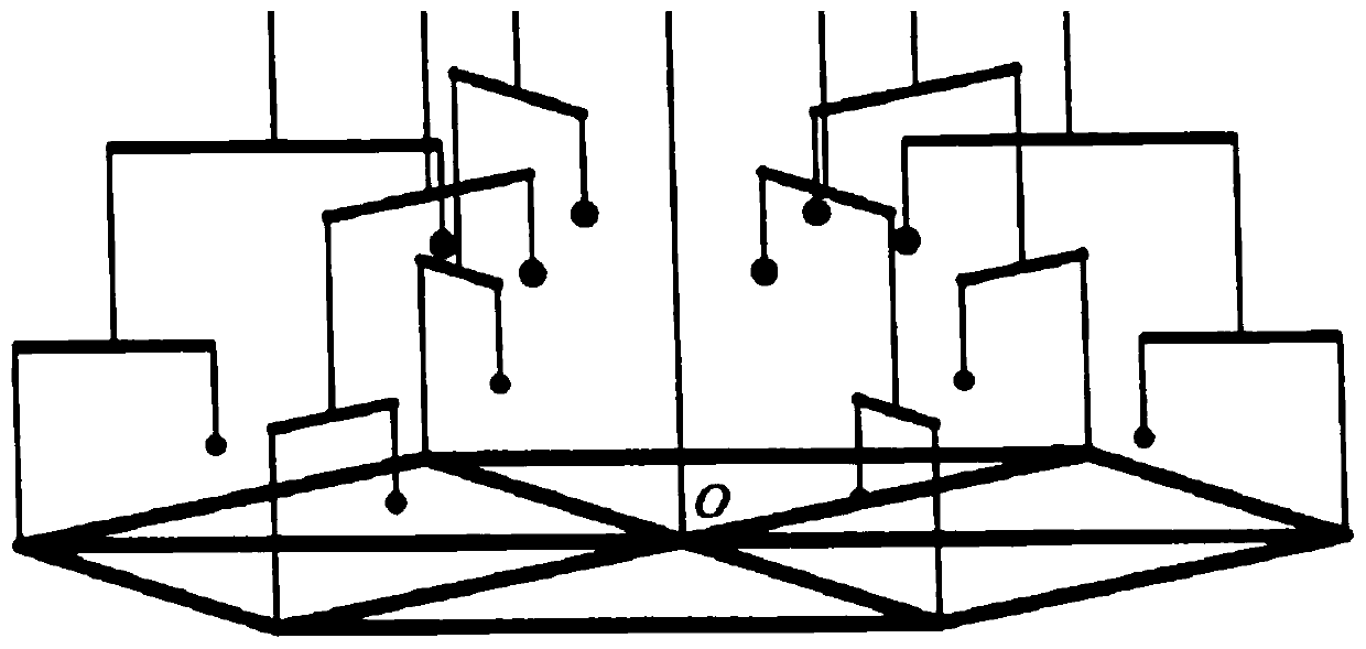
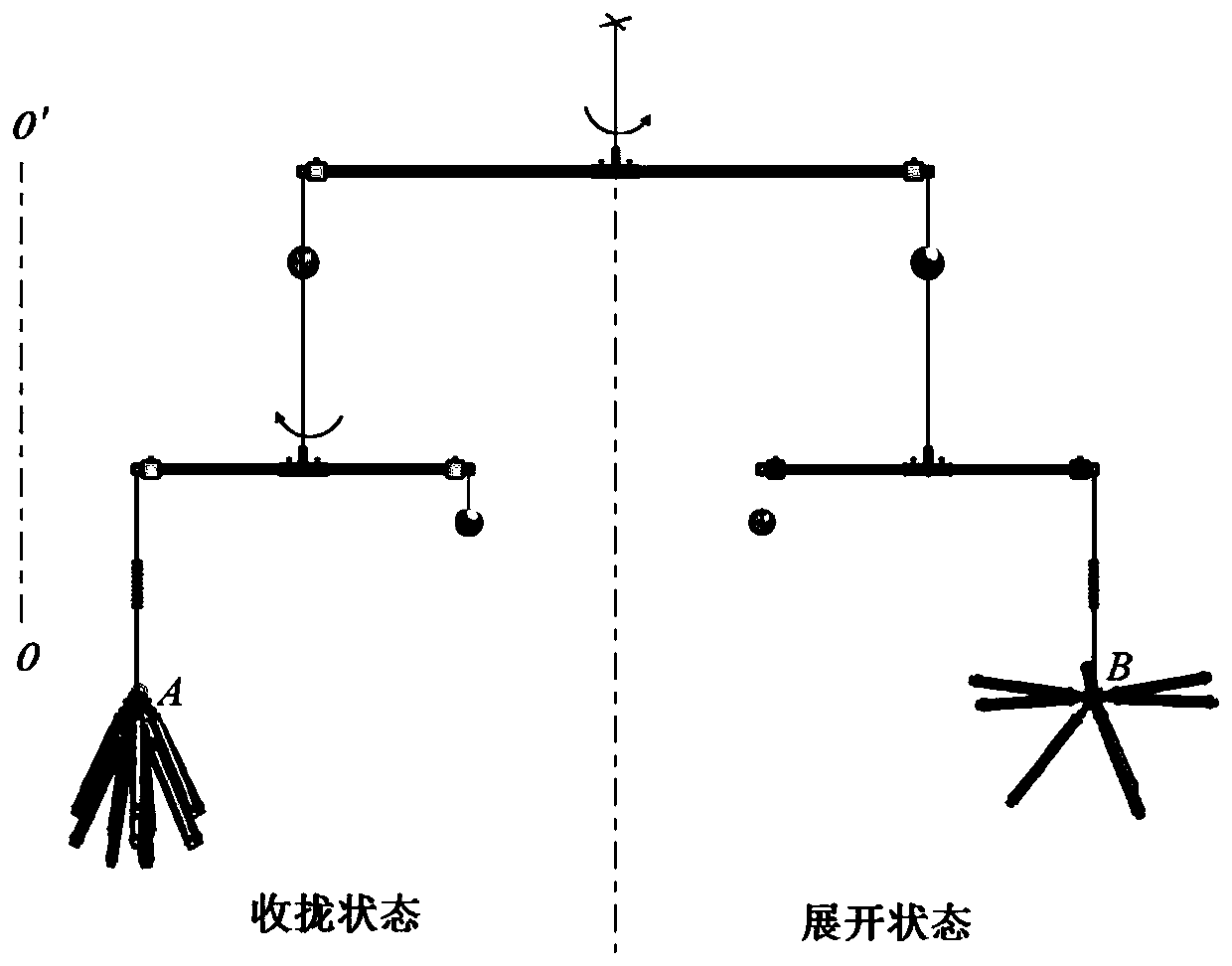
[0023] The schematic diagram of the ground gravity unloading system of the space expandable structure of the present invention is as follows Figure 1~3 As shown, including counterweights 1 and 2, lightweight suspension rods 3 and 4, ropes 5, lightweight soft springs 6, T-shaped sleeves 7, and telescopic adjustment sleeves 8, each unloading point is passed through an independent set of rods A combination of counterweights is used to implement gravity unloading. The main part of the unloading system is composed of the lower layer light suspension rod 3, the upper layer light suspension rod 4, the rope 5 and the counterweight 1 and 2...


PUM


Abstract

The invention provides a rod system unloading system of a ground zero gravity test of a large space circumferentially-expandable structure, which comprises light suspension rods, a rope, a counterweight, a telescopic adjusting sleeve, a T-shaped sleeve and the like. The effective unloading of the expandable structure gravity is completed by the combination of rod systems and the counterweight, andthe light suspension rods rotate around the respective suspension points in the process of unfolding the expandable structure from the initial state to the final state, in the unfolding process, thesuspended structural nodes perform circumferential expansion motion in the connecting line direction of the initial state and the final state of the expandable structure, each set of rod system combination system performs equivalent gravity unloading on the unloading points of the structure, that is, each set of rod system combination system ensures the motion stability of each unloading point, and the interference of the local unloading point in the whole unloading system to the whole system is avoided. The component parts of the unloading system do not slide relative to each other, so that the influence caused by friction force on the unfolding movement of the expandable structure is eliminated.

Description

technical field [0001] The invention provides a ground unloading system of a circumferentially deployable structure, which is mainly applied to the ground zero-gravity deployment test and measurement of a large-scale deployable structure, and belongs to the field of mechanical technology. Background technique [0002] In order to meet the development needs of space science and communication technology, space structures are developing towards large size, high precision, and good controllability. Among them, space-deployable structures, such as space-deployable solar panels, truss systems, and antenna structures, have greatly improved space launch capabilities. Since the deployable structure is in a storage state in the launch chamber before it is launched into orbit, it needs to go through the unfolding process to reach the working state after launch into orbit. In order to ensure that the space deployable structure can be deployed smoothly and safely in orbit, it is necessa...

Claims


Application Information

Patent Timeline
IPC IPC(8): B64G7/00
CPCB64G7/00
Inventor 王晓凯杜江华崔琦峰周鑫李向华王中王刘天明
Owner SHANGHAI AEROSPACE SYST ENG INST
Why Eureka
Try Eureka