Bypass transformer switch operation CT secondary current loop switching method

A secondary current, bypass switch technology, applied in electrical components, emergency protection circuit devices, etc., can solve problems such as electrical injury to workers, protection of misoperation, and failure to take measures to prevent CT open circuit, so as to avoid electrical injury work. Personnel, the effect of preventing secondary open circuit

Active Publication Date: 2020-03-24
SHENZHEN POWER SUPPLY BUREAU
View PDF6 Cites 3 Cited by
  • Summary
  • Abstract
  • Description
  • Claims
  • Application Information

AI Technical Summary

Problems solved by technology

[0004] However, no matter how it is prevented, many problems often occur during the operation process: (1) The differential protection function connection piece is not temporarily withdrawn before the CT secondary current circuit is switched, resulting in protection malfunction (due to careless operation during the operation process) There is a deviation, which will cause a differential current and cause a malfunction of the protection); (2) During the switching process of the CT secondary current circuit, measures to prevent CT open circuit are not done, resulting in CT secondary open circuit and electric injury to the staff; (3) Carrying out After the switching of the CT secondary current circuit is completed, the protection is not checked for abnormalities, and the differential protection function connection piece is blindly put in, resulting in protection malfunction (due to the deviation in the operation process, the differential current causes the protection malfunction to fail to reset); (4) In the whole work of switching the CT secondary current loop, it is not guaranteed that the loop is only grounded at one point

Method used


Image

  • Bypass transformer switch operation CT secondary current loop switching method
  • Bypass transformer switch operation CT secondary current loop switching method

Examples


Embodiment Construction

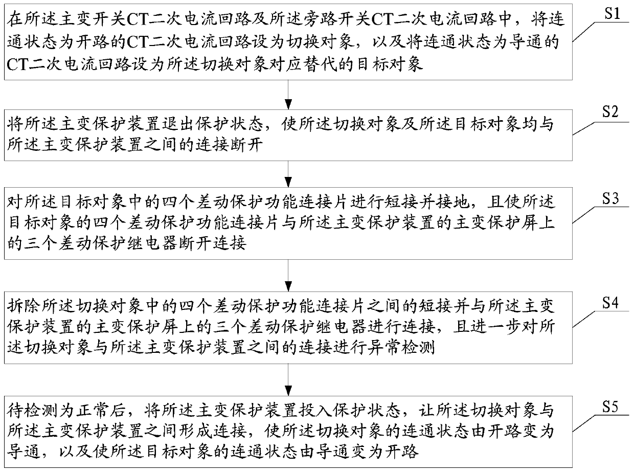
[0032] In order to make the object, technical solution and advantages of the present invention clearer, the present invention will be further described in detail below in conjunction with the accompanying drawings.

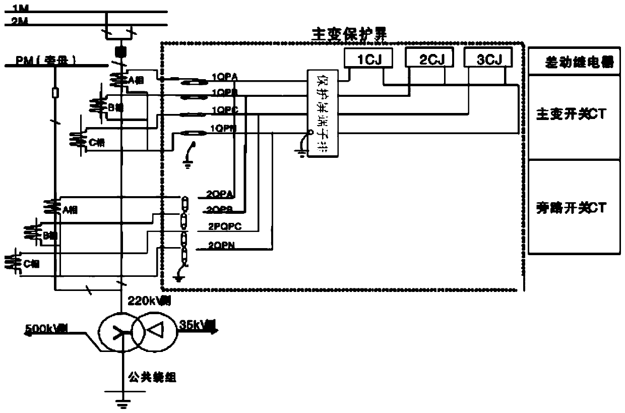
[0033] Such as figure 2 As shown, in the embodiment of the present invention, a bypass generation transformer switch operation CT secondary current circuit switching method is provided, which is used in a substation where the main transformer adopts a side interval, such as figure 1 shown; among them, the substation includes:

[0034] The main transformer connected to the main bus or bypass bus to supply power to the user side;

[0035] Main transformer protection device; among them, the main transformer protection device includes the main transformer protection screen, and the differential protection function connecting piece 1QPA, 1QPB, 1QPC, 1QPN, 2QPA, 2QPB, 2QPC, 2QPN and three differential protection function connecting pieces are formed on the main transf...


PUM


Abstract

The invention provides a bypass transformer switch operation CT secondary current loop switching method comprising the following steps: in a main transformer switch and bypass switch CT secondary current loop, setting a connection state as an open circuit as a switching object, and setting a connection state as a conduction as a target object; the main transformer protection device exiting from the protection state; short-circuiting and grounding the differential protection function connecting sheet in the target object, and disconnecting the target object from the main transformer protectiondevice; short circuits among the four differential protection function connecting pieces in the switching object and connecting with the main transformer protection device, and further carrying out the abnormality detection on connection; and after the detection is normal, putting the main transformer protection device into a protection state, so that the switching object is connected with the main transformer protection device, the switching object is changed from an open circuit to conduction, and the target object is changed from conduction to open circuit. By implementing the method, the problems existing before and after switching of an existing CT secondary current loop can be solved, and hidden dangers can be found in time.

Description

technical field [0001] The invention relates to the technical field of relay protection, in particular to a method for switching secondary current circuits of CTs operated by bypass transformer switches. Background technique [0002] In some substation constructions there are complete side bays, the main function is to replace them with complete side bays when a certain bay of the substation needs to be overhauled under the premise of no power outage and no impact on user power supply. At present, the bypass line interval is replaced by a complete set (including protection, switch, operation circuit, CT circuit, etc.), while the bypass can only replace the switch when replacing the transformer interval, and cannot replace the protection, that is, when the transformer switch needs to be overhauled, the load The required main transformer cannot be shut down. [0003] Such as figure 1 As shown in FIG. 2 , it is a schematic diagram of the connection of the main transformer of ...

Claims


Application Information

Patent Timeline
Patent Type & Authority Applications(China)
IPC IPC(8): H02H7/045
CPCH02H7/045
Inventor 王世祥吴海涛雷强刘自华
Owner SHENZHEN POWER SUPPLY BUREAU
Why Eureka
Try Eureka