Standby-state NR cell measurement method and standby-state NR cell measurement device

A technology of cell measurement and machine state, applied in the field of communication, can solve the problems of NR cell time and location arrangement and calculation complexity, and achieve the effects of saving receiving power consumption, shortening wake-up time, and avoiding repeated calculations

Active Publication Date: 2020-03-24
SPREADTRUM COMM (SHANGHAI) CO LTD
View PDF4 Cites 6 Cited by
  • Summary
  • Abstract
  • Description
  • Claims
  • Application Information

AI Technical Summary

Problems solved by technology

[0003] In the existing IDLE, there are many variables to determine the time and location arrangement of NR cell measurement, which is related to the SMTC configuration of each frequency point, which makes the calculation of time and location arrangement for NR cell measurement complicated under IDLE.

Method used


Image

  • Standby-state NR cell measurement method and standby-state NR cell measurement device
  • Standby-state NR cell measurement method and standby-state NR cell measurement device
  • Standby-state NR cell measurement method and standby-state NR cell measurement device

Examples


Embodiment 1

[0067] refer to image 3 , image 3 Embodiment 1 provides a method for measuring NR cells in a standby state, the method is performed by an NR terminal, and the method is as follows image 3 shown, including the following steps:

[0068] In step S301, the NR terminal obtains the SSB configuration of the serving cell and the PO configuration of the paging time.

[0069] In step S302, the NR terminal generates a prearranged pattern for cell measurement according to the SSB configuration and the PO configuration.

[0070] For the specific implementation method of the above step S302, reference may be made to the description of the following embodiments.

[0071] In step S303, the NR terminal quickly selects the frequency point and the time position to be measured from the prearranged pattern according to the given time α at any time.

[0072] The implementation method of the above step S303 may specifically include:

[0073] When the NR terminal is on standby, based on the p...

Embodiment 2

[0083] Embodiment 2 of the present application provides a specific implementation method of step S302 in Embodiment 1, see Figure 4 , specifically may include the following steps:

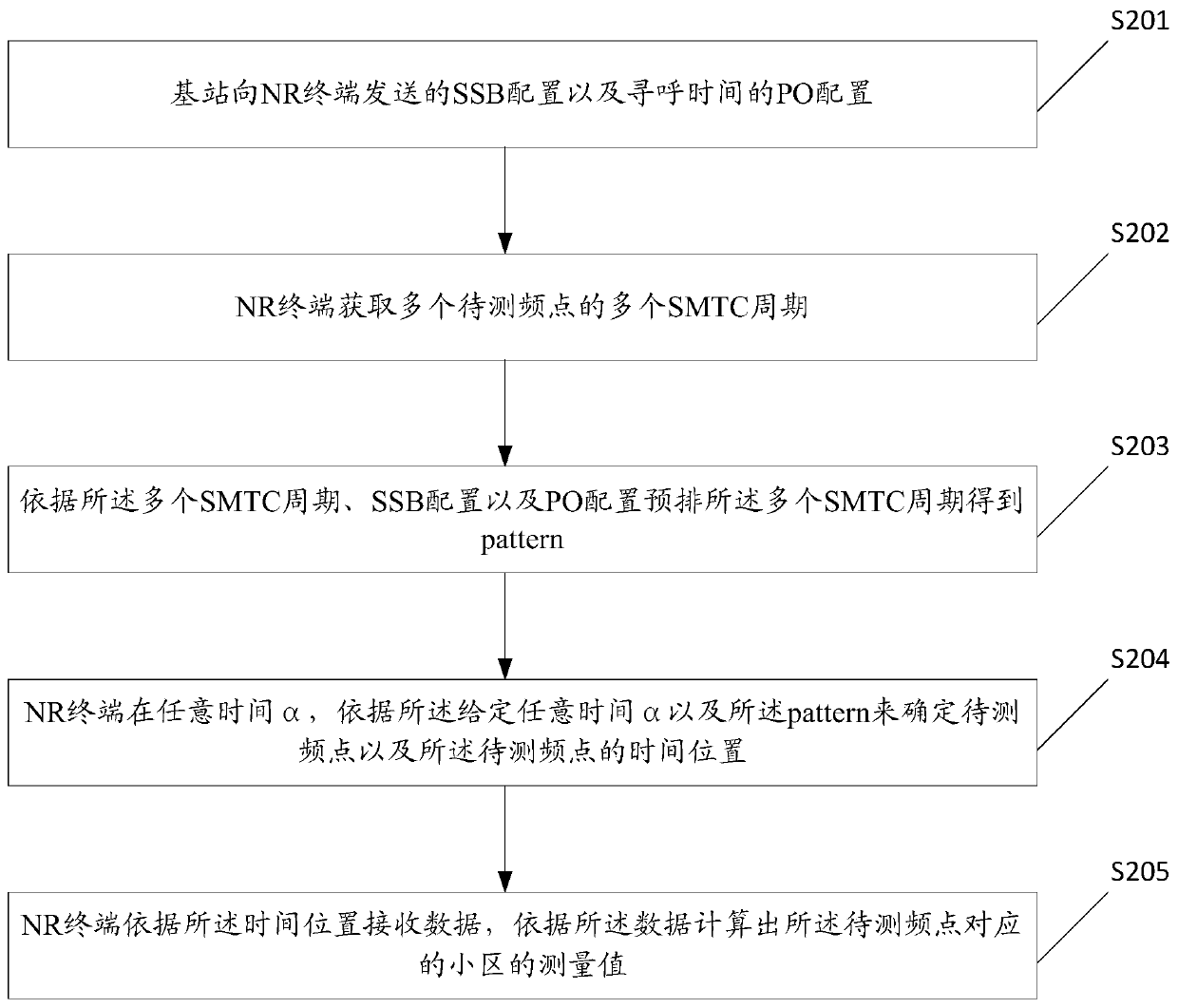
[0084] In step S401, the NR terminal acquires multiple SMTC periods of multiple frequency points to be tested.

[0085] In step S402, the NR terminal divides the pattern into three windows, and the three windows are window x, window y, and window z respectively.

[0086] The implementation method of the above step S402 may specifically include:

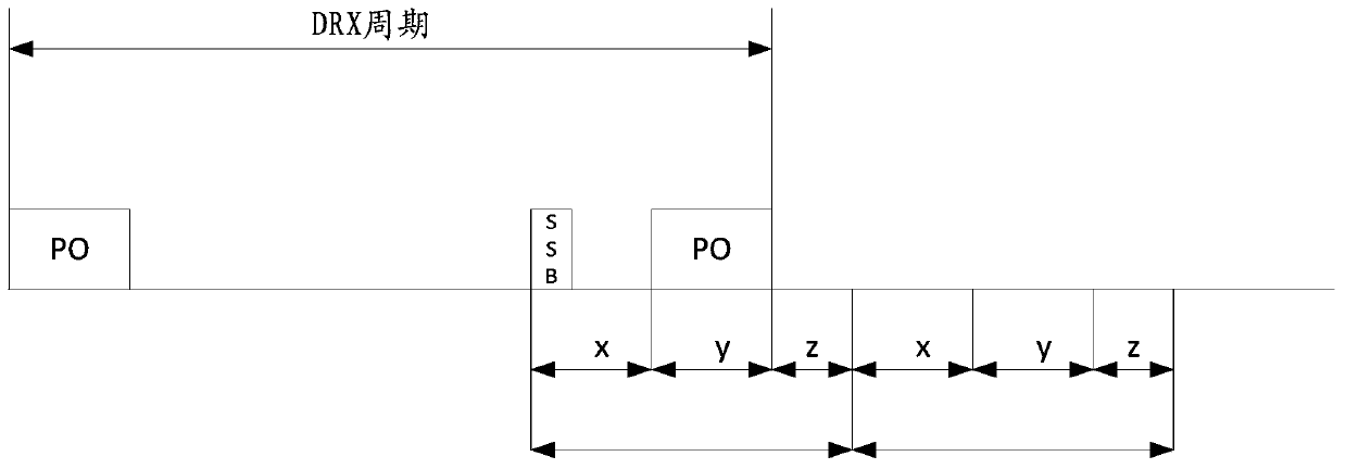
[0087] The NR terminal determines that the starting time point of the SSB of the serving cell is the starting time of the pattern, and divides the pattern into three windows, the starting time of the SSB to the starting time of the PO is window x, and the receiving window of the PO is window y, and the remaining time of the pattern is window z; the serving cell SSB is a group of SSBs closest to the PO before receiving the PO (such as Figure 2A SSB sho...


PUM


Abstract

The embodiment of the invention discloses a standby -state NR cell measurement method. . The method comprises the steps that an NR terminal obtains SSB configuration of a service cell and PO configuration of paging time; a plurality of measurement time SMTC periods is acquired based on a synchronization signal block of a plurality of frequency points to be measured, and pre-arranging the pluralityof SMTC periods according to the plurality of SMTC periods, SSB configuration and PO configuration to obtain a blueprint pattern of the period; an NR terminal determines a to-be-measured frequency point and the time position of the to-be-measured frequency point at any time alpha according to the given any time alpha and the blueprint pattern; and the NR terminal receives data according to the time position, and calculates a measurement value of a cell corresponding to the to-be-measured frequency point according to the data. The technical scheme provided by the invention has the advantages that the calculation amount is reduced, and the energy consumption is reduced.

Description

technical field [0001] The present application relates to the technical field of communications, and in particular to a method and device for measuring NR cells in a standby state. Background technique [0002] IDLE (standby state) is a state of the terminal. The NR cell measurement refers to the measurement of the serving cell, the same-frequency adjacent cell, the inter-frequency adjacent cell or the inter-RAT system (inter-RAT), and calculates the measurement value of the cell. [0003] In the existing IDLE, there are many variables that determine the time and location arrangement of NR cell measurement, which is related to the SMTC configuration of each frequency point, which leads to complex calculation of the time and location arrangement of NR cell measurement under IDLE. Contents of the invention [0004] The embodiment of the present application provides a NR cell measurement method and related devices in the standby state. The method realizes the blueprint prear...

Claims


Application Information

Patent Timeline
Patent Type & Authority Applications(China)
IPC IPC(8): H04W36/00H04W52/02H04W76/28
CPCH04W36/00835H04W52/0248H04W76/28Y02D30/70
Inventor 吴晓荣
Owner SPREADTRUM COMM (SHANGHAI) CO LTD
Why Eureka
Try Eureka