A viscosity-reducing coalescence device based on the principle of mechanical shear and swirl

A mechanical shearing and coalescing device technology, which is applied in the direction of production fluid, wellbore/well components, earthwork drilling and production, etc., can solve the problems of increasing the viscosity of the produced fluid, the degree of oil emulsification, and the difficulty of water treatment, etc. To achieve the effect of increasing emulsification degree, reducing impact and improving performance

Inactive Publication Date: 2020-09-15
NORTHEAST GASOLINEEUM UNIV
View PDF8 Cites 1 Cited by
  • Summary
  • Abstract
  • Description
  • Claims
  • Application Information

AI Technical Summary

Problems solved by technology

[0003] The purpose of the present invention is to provide a kind of viscosity reducing coalescence device based on mechanical shearing and swirling flow principle, this viscosity reducing coalescence device based on mechanical shearing and swirling flow principle is used to solve the problem due to the application of polymer flooding technology Polymerization in the production fluid increases the viscosity of the production fluid and the emulsification degree of the oil, which brings difficulties to the subsequent water treatment work

Method used


Image

  • A viscosity-reducing coalescence device based on the principle of mechanical shear and swirl
  • A viscosity-reducing coalescence device based on the principle of mechanical shear and swirl
  • A viscosity-reducing coalescence device based on the principle of mechanical shear and swirl

Examples


Embodiment Construction

[0041] The present invention will be further explained below in conjunction with the drawings:

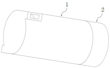
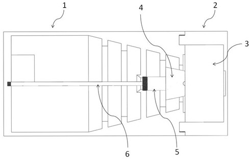
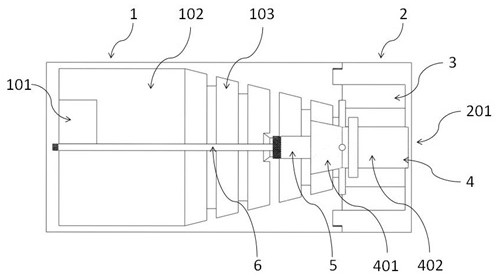
[0042] Combine Figure 1-Figure 16 As shown, this viscosity-reducing coalescence device based on the principle of mechanical shear and swirling flow is mainly divided into an upper working area surrounded by a viscosity-reducing coalescing outer cylinder 1 and a lower working area surrounded by a positioning sleeve 2. Cooperate with positioning booster 3, viscosity reducing coalescing sleeve 4, oil lead pipe 5 and lead rod 6 to realize viscosity reduction and coalescence. The swirling work space composed of the viscosity-reducing coalescing outer cylinder 1 and the internal components of the viscosity-reducing coalescing sleeve 4, etc., includes the surface of the lead rod and the lead pipe coated with lipophilic materials, as well as the viscosity-reducing shearing ladder 104 and increasing The design of the pressure ladder realizes the effect of viscosity reduction and coalescence ...


PUM


Abstract

The invention relates to a viscosity reduction and coalescence device based on a mechanical shearing and cyclone principle. The device comprises a viscosity reduction and coalescence outer cylinder, apositioning sleeve, a positioning supercharging platform, a viscosity reduction and coalescence sleeve, an oil guide pipe and an oil guide rod; the lower end of the viscosity reduction and coalescence outer cylinder is connected with the positioning sleeve; a tangential inlet is arranged at the upper end of a coalescence cavity; a viscosity reduction and coalescence cone is matched with a viscosity reduction and shearing platform; a bearing positioning disc is arranged at the bottom of the positioning sleeve; the positioning supercharging platform is fixed on the bearing positioning disc; theviscosity reduction and coalescence sleeve comprises an oil guiding conical pipe, a coalescence pipe and a positioning rod; the oil guiding conical pipe is arranged at the upper part of the coalescence pipe; the coalescence pipe is centrally arranged in the positioning supercharging platform; an annular supercharging and shearing ladder platform is arranged outside the upper end of the coalescence pipe; the supercharging and shearing ladder platform is matched with the viscosity reduction and shearing ladder platform at the lower end of a conical cavity; the positioning rod is connected withthe positioning supercharging platform; and coalescence guide plates are uniformly arranged on the inner wall of the oil guiding conical pipe. According to the device, viscosity reduction and coalescence are realized in the same device, and viscosity reduction treatment on polymer solution and coalescence treatment on oil drops are realized.

Description

Technical field: [0001] The invention relates to a viscosity-reducing coalescence device applied in the fields of petroleum, chemical industry and the like, and specifically relates to a viscosity-reducing coalescence device based on the principles of mechanical shear and swirling flow. Background technique: [0002] With the continuous development of the national economy, the demand for oil in today's society is increasing year by year, while the amount of oil reserves is gradually decreasing. After oilfields have experienced primary, secondary, and tertiary oil recovery, the water cut of the produced fluid has continued to increase. Most of the oilfields in my country have entered the stage of high water cut development. In order to improve the recovery rate of crude oil, new oil displacement technologies have been continuously proposed. Due to its own viscosity characteristics, polymer solution has the functions of reducing the longitudinal penetration of the formation, loweri...

Claims


Application Information

Patent Timeline
Patent Type & Authority Patents(China)
IPC IPC(8): E21B43/34E21B43/38E21B43/16
CPCE21B43/16E21B43/34E21B43/38
Inventor 刘扬卜凡熙陈双庆蒋明虎官兵邢雷
Owner NORTHEAST GASOLINEEUM UNIV
Why Eureka
Try Eureka