Al technical title is built by PatSnap Al team. It summarizes the technical point description of the patent document.
A transformer and functional technology, applied in the field of transformers with anti-theft function, can solve the problems of economic loss in the power sector, affect normal power consumption, transformer theft, etc., achieve the effect of improving the anti-theft effect, improving the degree of intelligence, and ensuring stability
Active Publication Date: 2020-03-27
ANHUI ZHONGBIAN TRANSFORMER
View PDF4 Cites 6 Cited by
Summary
Abstract
Description
Claims
Application Information
AI Technical Summary
This helps you quickly interpret patents by identifying the three key elements:
Problems solved by technology
Method used
Benefits of technology
Problems solved by technology
[0002] Transformer is a device that uses the principle of electromagnetic induction to change AC voltage. The main components are primary coil, secondary coil and iron core (magnetic core). The main functions are: voltage conversion, current conversion, impedance conversion, isolation, voltage stabilization (magnetic Saturated transformers), etc., can be divided into: power transformers and special transformers (electric furnace transformers, rectifier transformers, power frequency test transformers, voltage regulators, mining transformers, audio transformers, intermediate frequency transformers, high frequency transformers, impact transformers, instrument transformers, etc. Transformers, electronic transformers, reactors, mutual inductors, etc.), but the existing transformers have poor anti-theft effects, and it is easy to cause the transformer to be stolen during use, which not only affects people's normal electricity consumption, but also provides The power sector brings huge economic losses, for this reason, we propose a transformer with anti-theft function
Method used
Image
Click on the blue label to locate the original text in one second.
Reading with bidirectional positioning of images and text.
Examples
Embodiment Construction
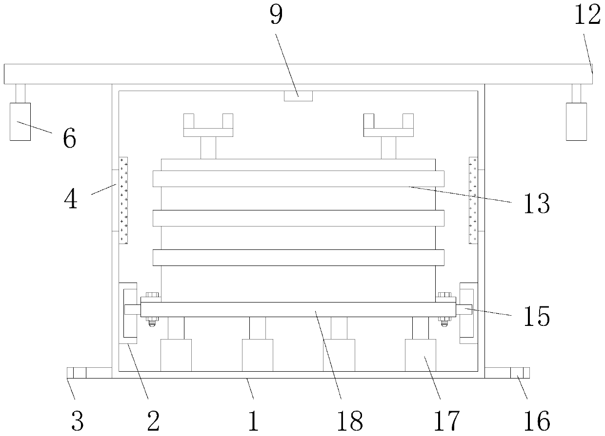
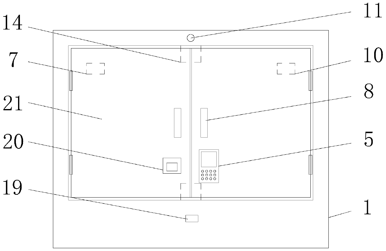
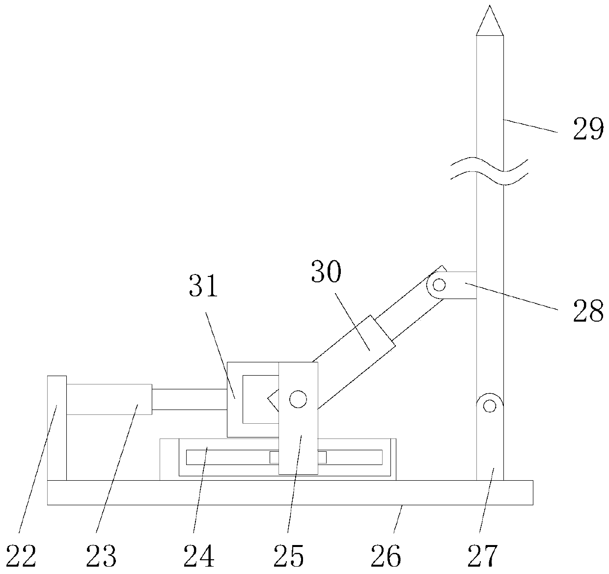
[0019] The following will clearly and completely describe the technical solutions in the embodiments of the present invention with reference to the accompanying drawings in the embodiments of the present invention. Obviously, the described embodiments are only some, not all, embodiments of the present invention. Based on the embodiments of the present invention, all other embodiments obtained by persons of ordinary skill in the art without making creative efforts belong to the protection scope of the present invention.
[0020] In the description of this application, it should be noted that, unless otherwise clearly specified and limited, the terms "installed", "set with", "connected", etc. should be understood in a broad sense, such as "connected", which can be a fixed connection , can also be detachably connected, or integrally connected; can be mechanically connected, can also be electrically connected; can be directly connected, can also be indirectly connected through an i...
PUM
Abstract
A transformer with an anti-theft function comprises a protection box and a supporting plate, a 4G communication module is fixedly connected to the middle end at the top of an inner cavity of the protection box, and two movable doors with handles fixedly installed on the front surfaces are movably connected to the upper end of the front surface of the protection box through hinges, and a movable door is located at the left side of the protection box. According to the invention, by arranging a fingerprint unlocking device, a password unlocking device and an electromagnetic lock, the safety can be improved; by arranging a vibration sensor, and when the protection box is vibrated, a camera can be automatically started to record the surrounding environment, so that the movable doors are prevented from being opened forcedly; and by arranging the supporting plate, a first connecting rod, a first electric telescopic rod, a second connecting rod, a second sliding block, a rotating shaft, a second electric telescopic rod, a fourth connecting rod, a third connecting rod, a first stop rod, a fifth connecting rod and a second stop rod are arranged, lawbreakers can be trapped between the secondstop rod and the protection box, and the polices are convenient to capture the lawbreakers.
Description
technical field [0001] The invention relates to the technical field of transformers, in particular to a transformer with anti-theft function. Background technique [0002] The transformer is a device that uses the principle of electromagnetic induction to change the AC voltage. The main components are the primary coil, the secondary coil and the iron core (magnetic core). The main functions are: voltage conversion, current conversion, impedance conversion, isolation, voltage stabilization (magnetic Saturated transformers), etc., can be divided into: power transformers and special transformers (electric furnace transformers, rectifier transformers, power frequency test transformers, voltage regulators, mining transformers, audio transformers, intermediate frequency transformers, high frequency transformers, impact transformers, instrument Transformers, electronic transformers, reactors, mutual inductors, etc.), but the existing transformers have poor anti-theft effects, and i...
Claims
Application Information
Patent Timeline
Application Date:The date an application was filed.
Publication Date:The date a patent or application was officially published.
First Publication Date:The earliest publication date of a patent with the same application number.
Issue Date:Publication date of the patent grant document.
PCT Entry Date:The Entry date of PCT National Phase.
Estimated Expiry Date:The statutory expiry date of a patent right according to the Patent Law, and it is the longest term of protection that the patent right can achieve without the termination of the patent right due to other reasons(Term extension factor has been taken into account ).
Invalid Date:Actual expiry date is based on effective date or publication date of legal transaction data of invalid patent.