
Incoming cable restraining device on box-type transformer

A box-type transformer and restraint device technology, which is applied to the transformer/inductor casing, transformer/inductor parts, circuits, etc., can solve the problems of reducing equipment safety, large swing range, and easy to fall off, etc., to reduce Oscillation range, effective sealing, and the effect of reducing springback

Active Publication Date: 2020-03-27
SHANDONG TAISHAN ELECTRICAL ENG & EQUIP CO LTD
View PDF9 Cites 0 Cited by
  • Summary
  • Abstract
  • Description
  • Claims
  • Application Information

AI Technical Summary

Problems solved by technology

The bottom of the side wall of the box transformer usually has a wire inlet hole, and the cable passes through the wire inlet hole and is bent upwards to connect with the connector of the equipment in the box. However, since the bent cable in the box has no equipment to fix it, its The swing range is large, and due to the strong toughness of the cable, it is easy to rebound into a straight state when it is bent upwards and is not fixed by a fixing device. If the upward bending part of the cable rebounds, it is easy to connect with the equipment Problems such as falling off occur, which reduces the safety of the equipment and makes the equipment unable to operate healthily

Method used


Image

  • Incoming cable restraining device on box-type transformer
  • Incoming cable restraining device on box-type transformer
  • Incoming cable restraining device on box-type transformer

Examples


Embodiment Construction

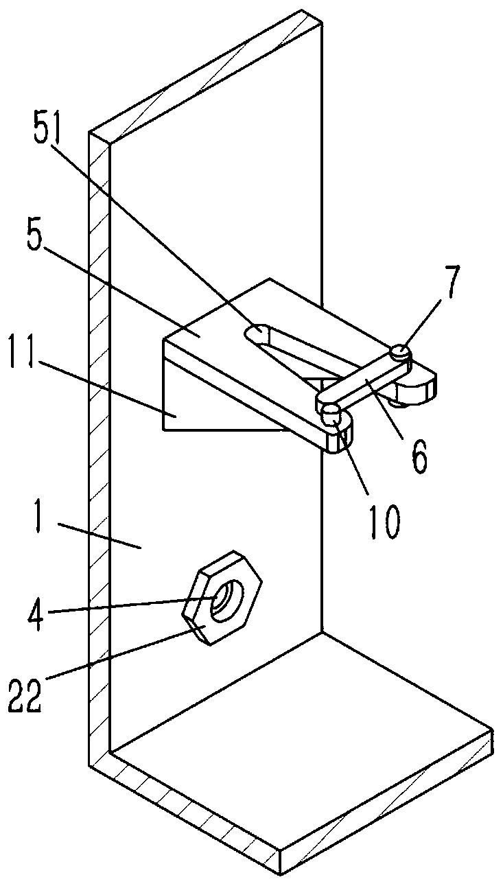
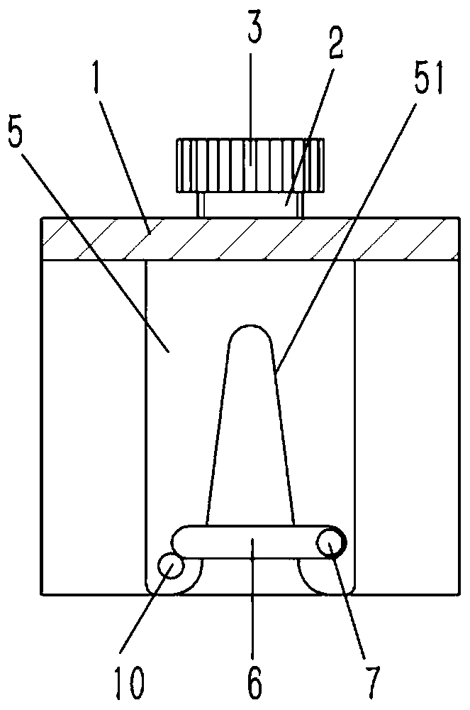
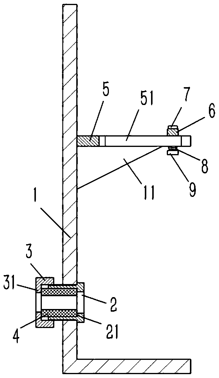
[0017] Example: see figure 1 , 2 , 3, an incoming cable restraint device on a box-type transformer, including a box body 1 on the box-type transformer, the bottom of the side wall of the box body 1 is formed with an inlet hole, and the inner screw of the wire inlet hole of the box body 1 Connected with an external thread sleeve 2, the inner end of the external thread sleeve 2 is formed with a flange 22, the flange 22 is against the inner wall of the box body 1, and the outer end of the external thread sleeve 2 is exposed to the outer wall of the box body 1 and is screwed with an inner A threaded sleeve 3, the inner wall of the externally threaded sleeve 2 is formed with an annular groove 21 that runs through the outer end surface of the externally threaded sleeve 2, and an annular rubber sleeve 4 is inserted into the annular groove 21 of the externally threaded sleeve 2. The outer end of the threaded sleeve 3 is formed with an annular end cap 31, and the end cap 31 abuts agai...


PUM


Abstract

The invention discloses an incoming cable restraining support on a box-type transformer. The box-type transformer comprises a box body on the box-type transformer, wherein a wire inlet hole is formedin the bottom of the side wall of the box body; an external thread bushing is screwed in the wire inlet hole of the box body; a flange is formed at the inner end of the external thread bushing; the flange abuts against the inner wall of the box body; the outer wall, exposed out of the box body, of the outer end of the outer threaded sleeve is in threaded connection with an inner threaded sleeve; an annular groove penetrating through the outer end face of the outer threaded sleeve is formed in the inner wall of the outer threaded sleeve; an annular rubber sleeve is inserted into the annular groove of the outer threaded sleeve; and an annular end cover is formed at the outer end of the inner threaded sleeve and abuts against the outer end face of the rubber sleeve. Through compression and expansion of the rubber sleeve, the incoming cable restraining support on a box-type transformer can restrain the incoming cable and achieve effective sealing, at the same time adds the restraining support to reduce the swing range of the cable, and utilizes the blocking strip to block the cable to reduce the rebound condition of the cable.

Description

Technical field: [0001] The invention relates to the technical field of box-type transformers, and more specifically relates to a restraint device for incoming cables on a box-type transformer. Background technique: [0002] Box-type transformers (usually referred to as "box transformers") concentrate the design of traditional transformers in box-type housings, with small size, light weight, low noise, low loss, and high reliability. They are widely used in residential quarters, commercial centers, light Stations, airports, factories, mines, enterprises, hospitals, schools and other places. The bottom of the side wall of the box transformer usually has a wire inlet hole, and the cable passes through the wire inlet hole and is bent upwards to connect with the connector of the equipment in the box. However, since the bent cable in the box has no equipment to fix it, its The swing range is large, and due to the strong toughness of the cable, it is easy to rebound into a straig...

Claims


Application Information

Patent Timeline
Patent Type & Authority Applications(China)
IPC IPC(8): H01F27/02H01F27/04
CPCH01F27/02H01F27/022H01F27/04
Inventor 潘建礼
Owner SHANDONG TAISHAN ELECTRICAL ENG & EQUIP CO LTD
Learn More