Slingshot with sighting unit
A sight and slingshot technology, which is applied in the field of sports and competitive toys, can solve the problems that the shooting angle of the projectiles cannot be guaranteed, the accuracy of the slingshot is difficult to be guaranteed, and the elongation of the elastic belt of the projectile bag is difficult to ensure. Speed, shooting stability, and the effect of improving accuracy
- Summary
- Abstract
- Description
- Claims
- Application Information
AI Technical Summary
Problems solved by technology
Method used
Image
Examples
Embodiment 1
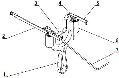
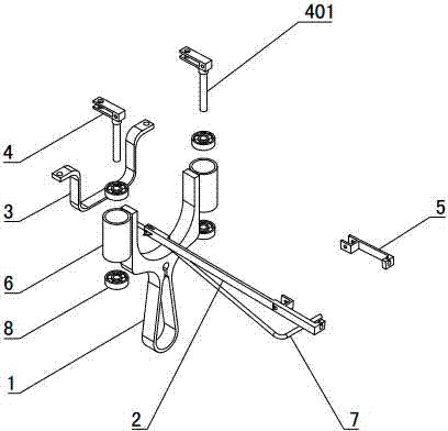
[0037] like Figure 1~2 As shown: the bow body 1 of the slingshot with sight is in the shape of "Y", the bow body 1 is provided with an aiming adjustment device, and the sighting device 2 is installed on the aiming adjustment device. One end of the elastic band is fixed on the aiming adjustment device, so that the aiming adjustment device drives the sight 2 to swing synchronously with the elastic band, which improves the accuracy and shooting stability of the slingshot, and makes the shooting accuracy of the slingshot less affected by personal operation factors.
[0038] The aiming adjustment device includes a horizontal adjustment mechanism and a vertical adjustment mechanism. The horizontal adjustment mechanism swings around the bow arm of the bow body 1, and the swing plane of the vertical adjustment mechanism is perpendicular to the swing plane of the horizontal adjustment mechanism.
[0039] As a further improvement, the axes of the swing shafts of the horizontal adjustme...
Embodiment 2
[0056] like Figure 7~8 As shown: the two bow arms of the bow body 1 are respectively provided with an ear, and the two ears respectively protrude between the two horizontal parts of the adjustment block 4 and are hinged; the connecting block 3 is "V" shaped, and the two ends of the connecting block 3 Bending outwards respectively, the two ends of the connecting block 3 respectively protrude between the two horizontal parts of the adjusting block 4 and are hinged. Take the vertical placement of the bow body 1 as an example, the sight 2 is arranged on the outside of the swing arm 5 on the left side, and the length of the sight 2 is 200 mm. The two ends of the sight 2 protrude respectively, the front sight 201 and the rear sight are located at the two ends of the sight 2 respectively, and the front sight 201 is fixed on the sight 2 . When the swing arm 5 is perpendicular to the plane where the bow body 1 is located, the distance between the sight 2 and the perpendicular line co...
Embodiment 3
[0058] like Figure 9 As shown: the aiming adjustment device includes a swing arm 5 respectively hinged on the two bow arms of the bow body 1 and a sight 2 installed on the swing arm 5 . The swing arm 5 is "匚" shape, and the upper ends of the two bow arms extend respectively between the two horizontal parts of the two swing arms 5 and are hinged. The other end of the swing arm 5 is used to install a rubber band, and each side of the projectile pocket has a rubber band respectively. Taking the bow body 1 placed vertically as an example, the sight 2 is arranged on the outside of the swing arm 5 on the left side. The two ends of the sight 2 protrude respectively, and the front sight 201 and the rear sight are located at the two ends of the sight 2 respectively. When the swing arm 5 is perpendicular to the plane where the bow body 1 is located, the distance between the sight 2 and the perpendicular line connecting the two bow arms is 50 mm. The rest of the structure, shape, ins...
PUM
 Abstract
Description
Claims
Application Information
 - R&D
- Intellectual Property
- Life Sciences
- Materials
- Tech Scout
- Unparalleled Data Quality
- Higher Quality Content
- 60% Fewer Hallucinations
Browse by: Latest US Patents, China's latest patents, Technical Efficacy Thesaurus, Application Domain, Technology Topic, Popular Technical Reports.
© 2025 PatSnap. All rights reserved.Legal|Privacy policy|Modern Slavery Act Transparency Statement|Sitemap|About US| Contact US: help@patsnap.com


