Calibration method for strapdown inertial navigation installation attitude of photoelectric tracking system

A technology of photoelectric tracking system and strapdown inertial navigation, which is applied in the direction of measuring device, navigation calculation tool, and navigation through speed/acceleration measurement, etc. Errors are not easy to guarantee and other issues

Active Publication Date: 2020-03-31
THE GENERAL DESIGNING INST OF HUBEI SPACE TECH ACAD
View PDF19 Cites 11 Cited by
  • Summary
  • Abstract
  • Description
  • Claims
  • Application Information

AI Technical Summary

Problems solved by technology

[0007] The above methods have some disadvantages. The first method is guaranteed by the mechanism, which has high requirements for structural design, processing and assembly, high cost, and requires multiple mechanical reference conversions, and the error is not easy to guarantee.
Both method 2 and method 3 need to be carried out in the field. First, a relatively open field is required. Among them, method 3 needs to fly a drone, which has more constraints on the field; Especially large photoelectric tracking system
In method 2, it is troublesome to measure the benchmark under the geographic system, and in method 3, there is a very high requirement for time synchronization accuracy, which is not easy to guarantee

Method used


Image

  • Calibration method for strapdown inertial navigation installation attitude of photoelectric tracking system
  • Calibration method for strapdown inertial navigation installation attitude of photoelectric tracking system
  • Calibration method for strapdown inertial navigation installation attitude of photoelectric tracking system

Examples


Embodiment Construction

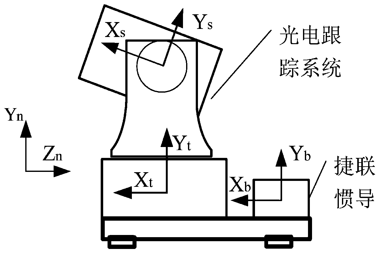
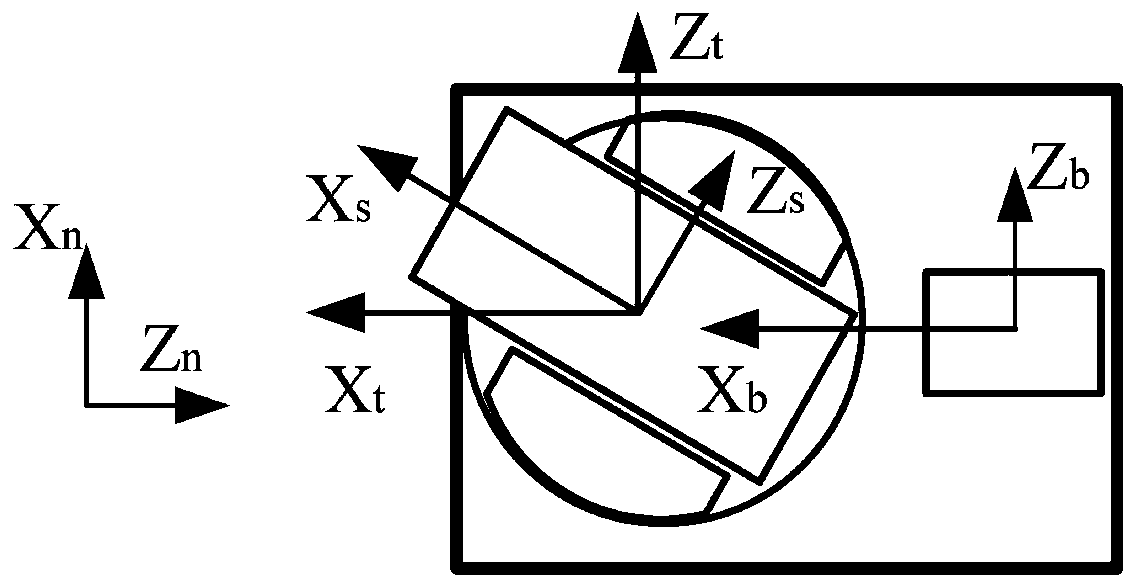
[0061] The present invention will be described in further detail below in conjunction with the accompanying drawings and embodiments.

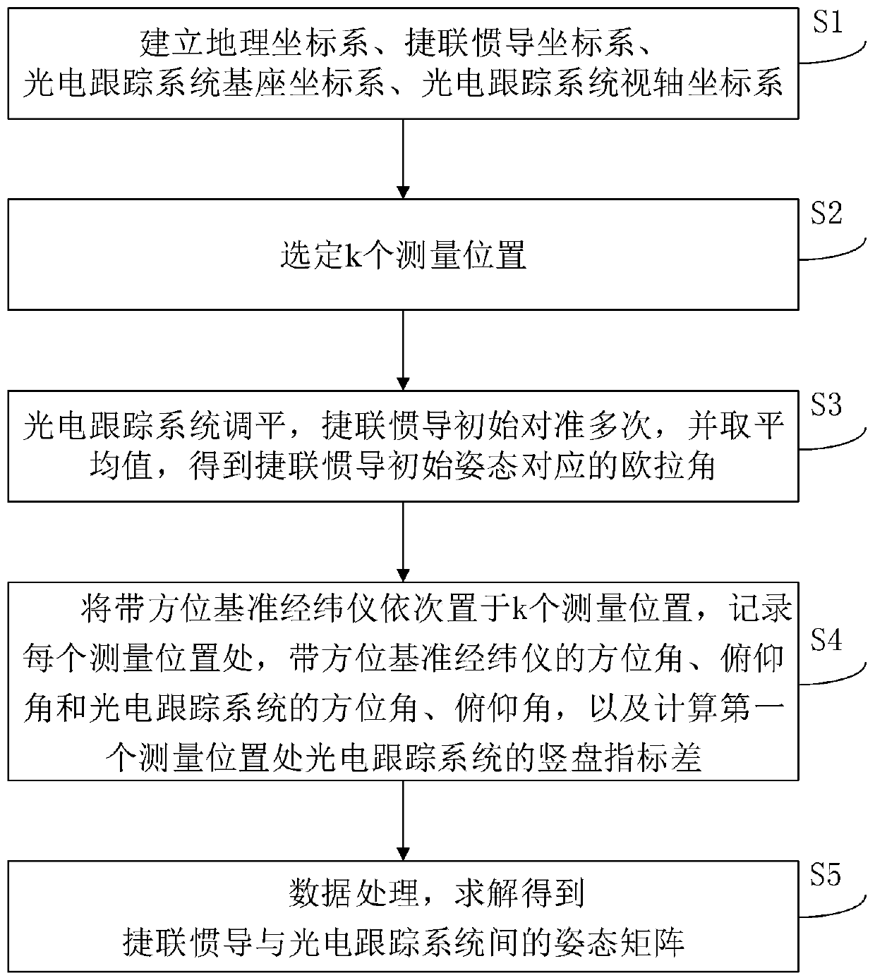
[0062] An embodiment of the invention provides a method for calibrating the installation attitude of a strapdown inertial navigation system for a photoelectric tracking system.

[0063] The present invention adopts gyro theodolite to provide azimuth and horizontal reference (or adopts the combination of autocollimating theodolite and north finder to provide azimuth and horizontal reference), and calibrates the attitude matrix between strapdown inertial navigation and photoelectric tracking system.

[0064] The train of thought of the present invention is: take the geographical coordinate system as a bridge, establish the connection between the two by seeking the expression of the boresight vector of each position under the strapdown inertial navigation and photoelectric tracking system; then calculate the photoelectric tracking system and strap...


PUM


Abstract

The invention discloses a calibration method for a strapdown inertial navigation installation attitude of a photoelectric tracking system. The calibration method comprises the following steps: establishing a coordinate system n system, a coordinate system b system, a coordinate system t system and a coordinate system s system; conducting the strapdown inertial navigation initial alignment for multiple times, obtaining the average value, and obtaining a strapdown inertial navigation initial attitude Euler angle; sequentially placing the theodolite with the azimuth reference at each measurementposition, completing alignment, recording an azimuth angle and a pitch angle of the theodolite with the azimuth reference and an azimuth angle and a pitch angle of a photoelectric tracking system, performing north-seeking for multiple times, recording a north-seeking result average value, and calculating a vertical disc index difference; establishing an attitude matrix vector r which is parallel to the visual axis of the photoelectric tracking system, takes a unit vector of which the starting point is the origin of the coordinate system, the coordinate of the vector r being vector r<s> in the s system, calculating the attitude matrix C<s><t>, i of from the t system and the s system, according to the vector r<s> and the C<s><t>, i, calculating the coordinate vector r<t>of thevector r in the t system, calculating the coordinate vector r<n>of the vector r in the n system, calculating the attitude matrix C<n> from the n system to the b system according to the Euler angle, calculating the coordinate vector r of the vector r in the b system according to the vector r<n> and C<n>, establishing a linear equation (as shown in the description) according to the vector r<t> and the vector r, and solving C<t> by combining with the k linear equations. The the method can be used for indoor calibration.

Description

technical field [0001] The invention relates to the field of photoelectric tracking system testing, in particular to a method for calibrating the installation attitude of a strapdown inertial navigation system for a photoelectric tracking system. Background technique [0002] The field of view of the photoelectric tracking system is usually several orders of magnitude, and it is difficult to directly capture the target. Before tracking the target, external information is required for guidance, such as radar or GPS information. Usually the external guidance information can be converted to spherical coordinates in the geographic coordinate system. In order to obtain the attitude of the carrier platform of the photoelectric tracking system relative to the geographic coordinate system, the inertial navigation system is installed on the carrier platform of the photoelectric tracking system and strapped down to the base. Inertial navigation measures the attitude of the carrier pla...

Claims


Application Information

Patent Timeline
Patent Type & Authority Applications(China)
IPC IPC(8): G01C25/00G01C21/16G01C21/20
CPCG01C25/00G01C21/16G01C21/20
Inventor 沈小龙庹文波刘源远胡黎明姜永亮张贵清李强武春风许彦刚雷杨吴伊玲王婉婷
Owner THE GENERAL DESIGNING INST OF HUBEI SPACE TECH ACAD
Why Eureka
Try Eureka