Display device, display control method, and storage medium

A display device and light device technology, applied in the direction of optical observation device, instrument arrangement, static indicator, etc., can solve the problem of image visual confirmation reduction and achieve the effect of visual confirmation improvement

Active Publication Date: 2020-04-03
HONDA MOTOR CO LTD
View PDF4 Cites 0 Cited by
  • Summary
  • Abstract
  • Description
  • Claims
  • Application Information

AI Technical Summary

Problems solved by technology

[0003] However, in the conventional HUD device, the display position of the image changes

Method used


Image

  • Display device, display control method, and storage medium
  • Display device, display control method, and storage medium
  • Display device, display control method, and storage medium

Examples


no. 1 approach

[0034] [the whole frame]

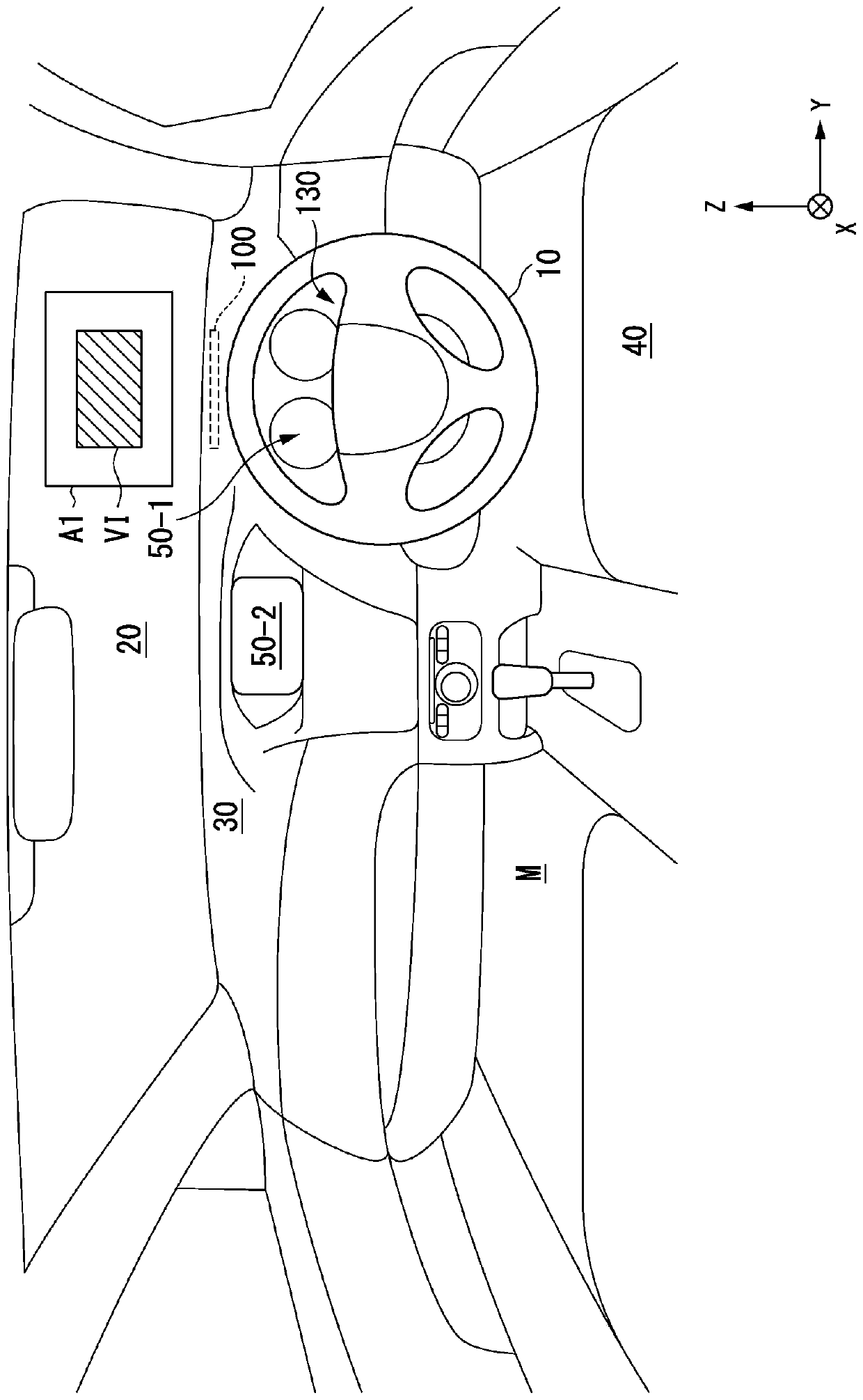
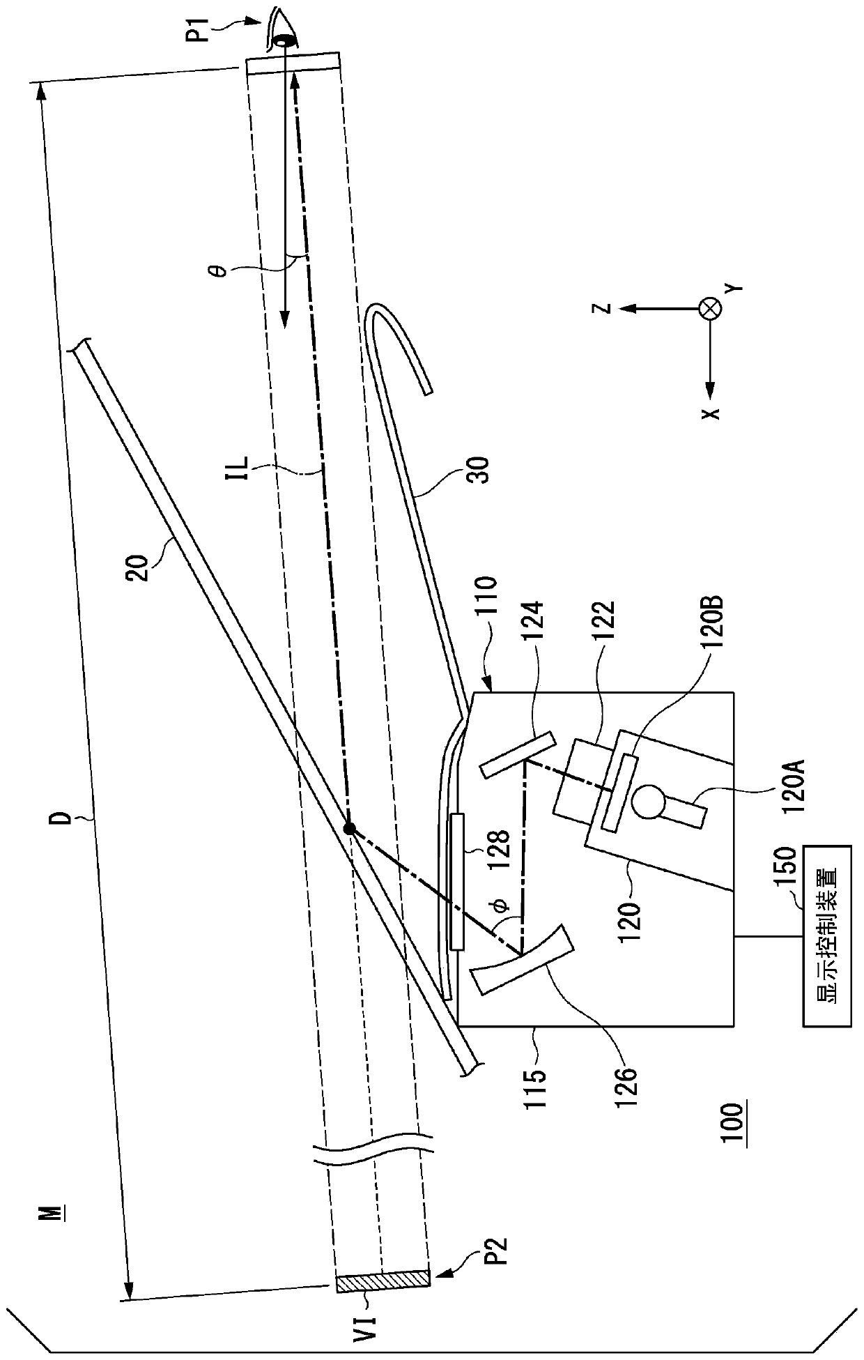
[0035] figure 1 It is a diagram illustrating an example of the configuration of a vehicle interior of a vehicle M equipped with the display device 100 according to the first embodiment. In the vehicle M, for example, a steering wheel 10 for controlling the steering of the vehicle M, a windshield (an example of a reflector) 20 for distinguishing the outside of the vehicle from the inside of the vehicle, and an instrument panel 30 are provided. The windshield glass 20 is a light-transmitting member. The display device 100 allows the driver seated in the driver's seat to visually recognize Virtual image VI.

[0036] The display device 100 visualizes, for example, an image of information for supporting the driver's driving as a virtual image VI for the driver to visually recognize. The information for supporting the driving of the driver includes, for example, information such as the speed of the vehicle M, the driving force distribution ratio, the e...

no. 2 approach

[0094] Next, a second embodiment of the display device will be described. The second embodiment is an embodiment in which the adjustment of the depression angle θ by driving the concave mirror actuator 182 by the optical system controller 170 and the adjustment of the depression angle θ using the light projection device 120 by the display controller are combined. Hereinafter, in the description of the display device 100# of the second embodiment, the same names and symbols are attached to the same structures as those of the display device 100 of the first embodiment, and the specific description here is omitted. Figure 11 It is a diagram showing a configuration example of display device 100# centering on display control device 150 in the second embodiment. Display device 100 # differs from display device 100 in that display control device 150 is provided with display form control unit 152 # instead of display form control unit 152 , and is provided with notification control u...


PUM


Abstract

The present invention provides a display device, a display control method, and a storage medium that can improve visual confirmation. The display device includes a light projection device which projects light including an image, an optical mechanism which is capable of adjusting a distance from a predetermined position to a position where the light is formed as a virtual image, a concave mirror which reflects light toward a reflector, a concave mirror actuator which adjusts a reflection angle of the concave mirror, and a control device which controls the light projection device and the concavemirror actuator, in which the control device adjusts a projection position on a projection surface of the light projected from the light projection device having an angle formed by a horizontal surface passing through a predetermined position on an image and a segment from the predetermined position to a position where the light is formed as a virtual image so as to curb fluctuation occurring dueto movement of a vehicle.

Description

technical field [0001] The invention relates to a display device, a display control method and a storage medium. Background technique [0002] Conventionally, there is known a head-up display device (hereinafter referred to as a HUD (Head Up Display) device) that displays an image related to information for the driver on the windshield (for example, Japanese Patent Laid-Open No. 2017-91115) . Using this HUD device, various signs indicating obstacles, alerts, and the direction of travel are superimposed and displayed on the predetermined position of the windshield with the scenery in front of the vehicle, so that the driver can maintain the direction of the line of sight while driving. ahead, while grasping various information displayed. [0003] However, in the conventional HUD device, the display position of the image changes due to the behavior of the vehicle, and thus the visibility of the displayed image may decrease. Contents of the invention [0004] The aspects o...

Claims


Application Information

Patent Timeline
IPC IPC(8): G02B27/01B60R1/00
CPCG02B27/0101B60R1/001G06F3/0484G06F3/011G06F3/0346G06F3/013G02B2027/011G02B2027/0159G02B2027/0161B60K35/00B60K37/02B60K2370/1529B60K2370/23B60K2370/31B60K2370/334G02B2027/0183G09G5/38G09G2340/0464G09G2354/00G09G2380/10G02B27/0149G02B27/0179G06F3/02
Inventor 东山匡史木村卓也川上慎司岩佐达也桑岛悠司
Owner HONDA MOTOR CO LTD
Why Eureka
Try Eureka