Speed reduction linkage type clamping mechanism and mobile phone support

A clamping mechanism and linkage technology, applied in the field of deceleration linkage clamping mechanism and mobile phone brackets, can solve the problems of limited model, difficult to clamp mobile phones, affecting the application range of mobile phone brackets, etc., to meet application requirements and linkage process. stable effect

Pending Publication Date: 2020-04-03
深圳市智高翔科技发展有限公司
View PDF0 Cites 2 Cited by
  • Summary
  • Abstract
  • Description
  • Claims
  • Application Information

AI Technical Summary

Problems solved by technology

In practical applications, the mobile phone is generally only clamped by the claws on both sides of the mobile phone holder. Due to the lack of supporting parts at the lower end of the mobile phone, it is difficult to clamp the mobile phone stably. The holding parts are generally fixed, and only rely on the jaws on both sides to perform opening and clamping actions. For mobile phones of different sizes, sometimes it is necessary to lift the mobile phone up to a certain height, or sink a certain distance, for example , Most of the buttons on the side of the mobile phone are set near the upper edge of the mobile phone. When the buttons on the side of the mobile phone are opposite to the grippers, the mobile phone needs to be lifted up to prevent the grippers from pressing the side buttons of the mobile phone. In the prior art, due to The supporting parts of the mobile phone holder cannot be moved, which leads to the limitation of the mobile phone models that the mobile phone holder can hold, which only affects the application range of the mobile phone holder, and it is difficult to meet the application needs and market demand

Method used


Image

  • Speed reduction linkage type clamping mechanism and mobile phone support
  • Speed reduction linkage type clamping mechanism and mobile phone support
  • Speed reduction linkage type clamping mechanism and mobile phone support

Examples


Embodiment approach

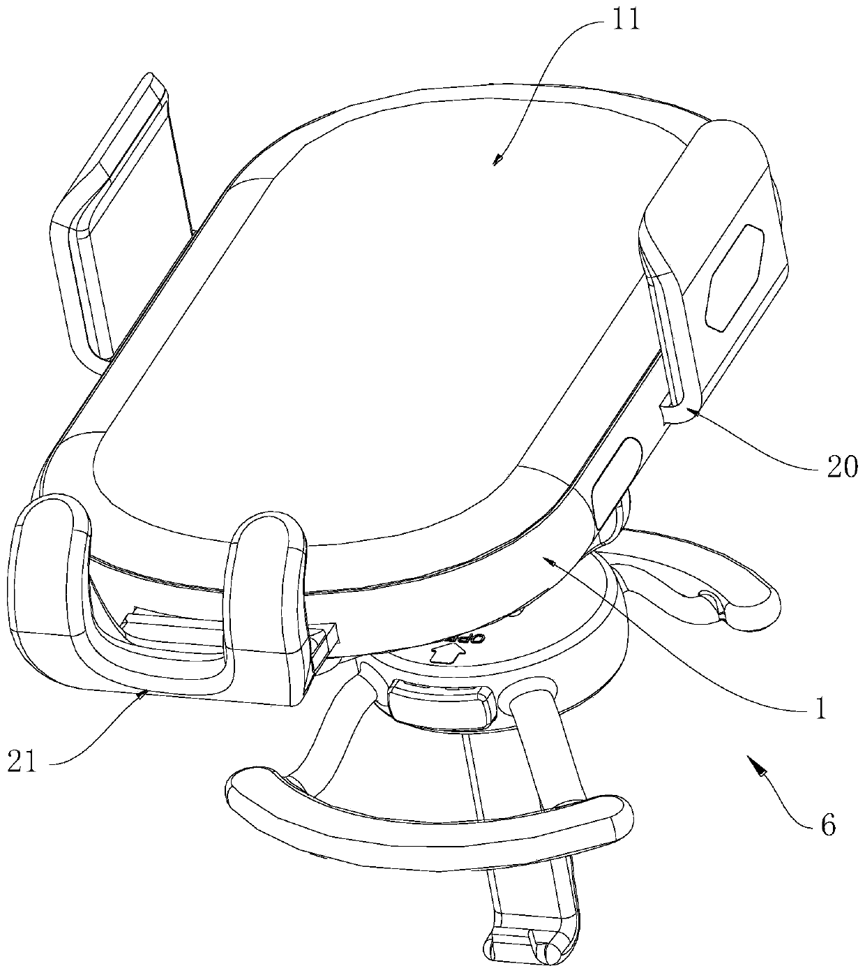
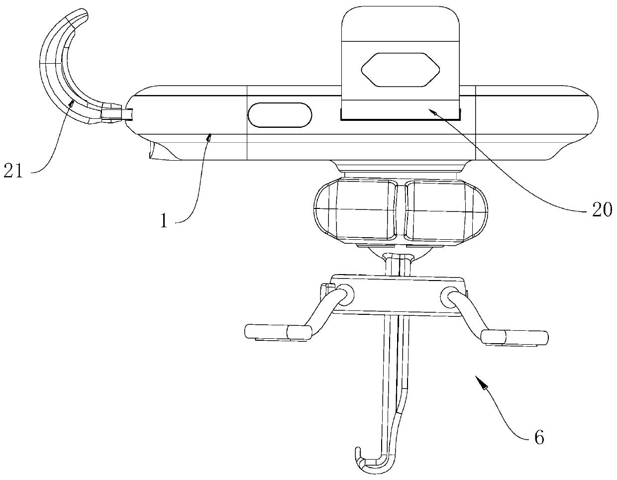
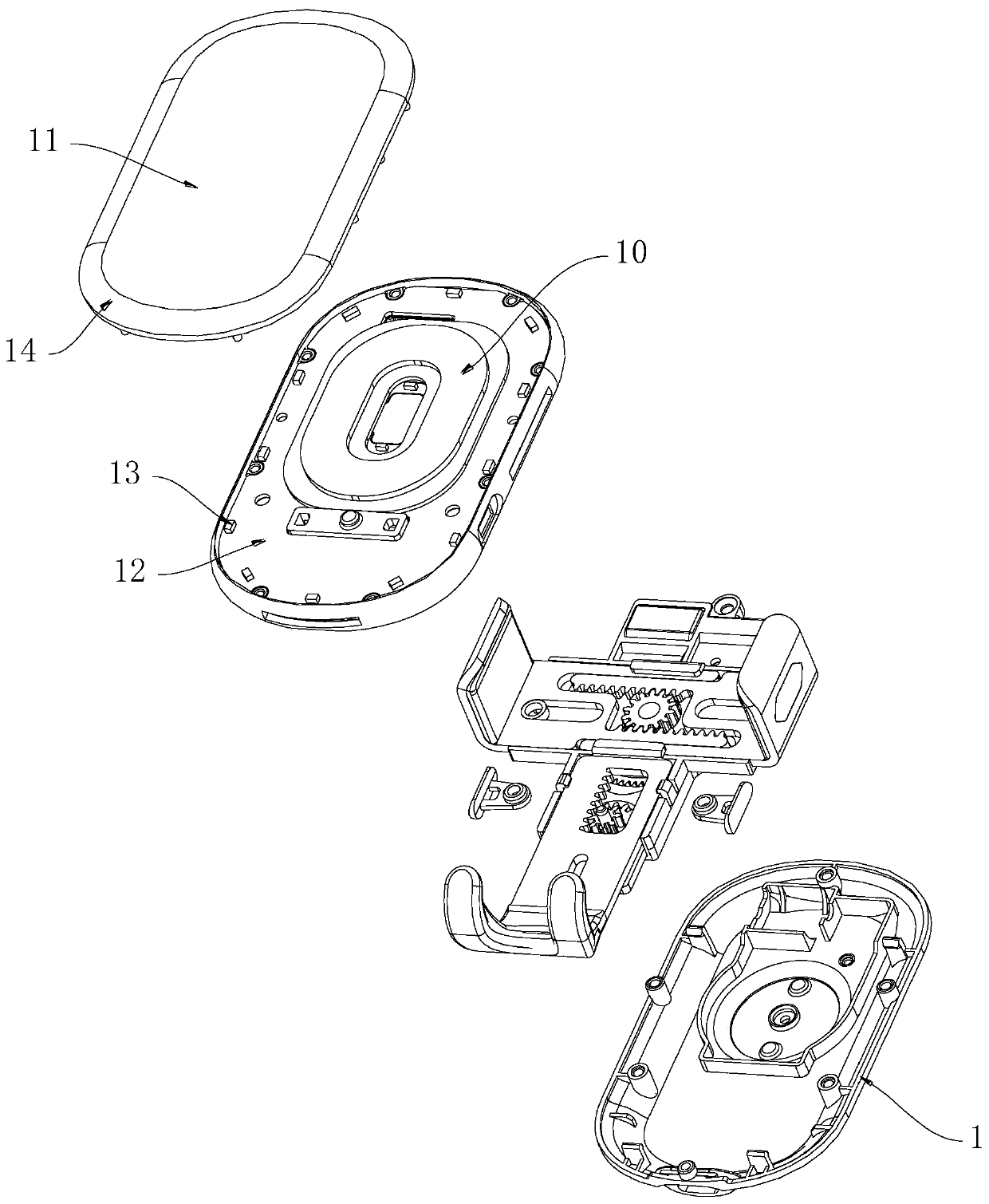
[0049] However, under another embodiment of the present invention, see Figure 10 , the longitudinal teeth 211 are located at the right edge of the opening 212, based on the above structure, when the drive gear 202 drives the two horizontal jaws 20 to open, the drive gear 202 drives the longitudinal straight rack 203 to approach The direction of the horizontal jaw 20 translates, while the reduction gear 204 drives the longitudinal arm 210 to decelerate and translate, and the translation direction of the longitudinal arm 210 is opposite to that of the longitudinal straight rack 203, that is, when the two horizontal jaws 20 When opened, the longitudinal jaws 21 perform a lowering action, and when the two transverse jaws 20 are clamped, the longitudinal jaws 21 perform a lifting action.

[0050] It can be seen that, in order to meet action requirements in different application scenarios, the longitudinal teeth 211 may be located at the left edge or the right edge of the opening 2...


PUM


Abstract

The invention discloses a speed reduction linkage type clamping mechanism. The speed reduction linkage type clamping mechanism comprises a bracket, wherein two transverse clamping jaws and a longitudinal clamping jaw are arranged on the bracket; the transverse clamping jaw comprises a transverse support arm; a transverse spur rack is formed at the end part of the transverse support arm; the two transverse spur racks are arranged in a staggered mode, and a driving gear is clamped between the two transverse spur racks. The two transverse spur racks are meshed with the driving gear; the longitudinal clamping jaw comprises a longitudinal support arm; a longitudinal spur rack is arranged above or below the longitudinal support arm; a reduction gear capable of rotating is arranged on the bracket; longitudinal teeth are formed on the longitudinal support arm; the longitudinal teeth are meshed with an output wheel of the reduction gear. When the driving gear rotates forwards or reversely, thetwo transverse clamping jaws are driven to be away from each other or close to each other, and the longitudinal clamping jaws are driven to slide in the longitudinal direction in a speed reduction mode through cooperation of the driving gear, the longitudinal support arm and the reduction gear. According to the speed reduction linkage type clamping mechanism, a mobile phone can be supported, the supporting action can be executed in a decelerating mode in the clamping process, and then stable and reliable linkage is achieved.

Description

technical field [0001] The invention relates to a mobile phone holder, in particular to a deceleration linkage clamping mechanism and a mobile phone holder. Background technique [0002] The mobile phone holder is a device used to clamp the mobile phone and support the mobile phone on the desktop, the center console of the car, etc. In practical applications, the mobile phone is generally only clamped by the claws on both sides of the mobile phone holder. Due to the lack of supporting parts at the lower end of the mobile phone, it is difficult to clamp the mobile phone stably. The holding parts are generally fixed, and only rely on the jaws on both sides to perform opening and clamping actions. For mobile phones of different sizes, sometimes it is necessary to lift the mobile phone up to a certain height, or sink a certain distance, for example , Most of the buttons on the side of the mobile phone are set near the upper edge of the mobile phone. When the buttons on the side...

Claims


Application Information

Patent Timeline
Patent Type & Authority Applications(China)
IPC IPC(8): H04M1/04
CPCH04M1/04
Inventor 朱长仙
Owner 深圳市智高翔科技发展有限公司
Why Eureka
Try Eureka