Multi-stage variable stiffness pneumatic soft actuator
A variable stiffness and actuator technology, applied in the direction of chucks, manipulators, manufacturing tools, etc., can solve the problems of small stiffness variation range, poor load capacity, slow response speed, etc., and achieve small size, wide load range, and light weight. Effect
Active Publication Date: 2022-05-31
JILIN UNIV
View PDF12 Cites 0 Cited by
- Summary
- Abstract
- Description
- Claims
- Application Information
AI Technical Summary
Problems solved by technology
[0005] The purpose of the present invention is to solve the problems of existing variable stiffness pneumatic soft actuators such as small stiffness variation range, slow response speed, poor load capacity, etc., and propose a multi-stage variable stiffness pneumatic soft actuator
Method used
View moreImage
Smart ImageViewing Examples
Examples
Embodiment Construction
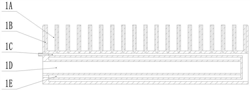
[0027] The inside of the first software rack 1 is provided with a first cavity 1C, a second cavity 1D, and a third cavity 1E; the second cavity 1D is located at
Login to View More PUM
 Abstract
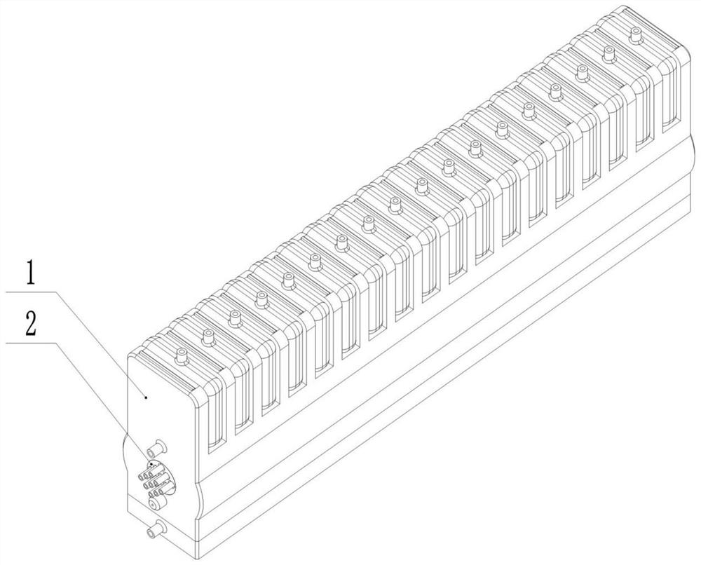
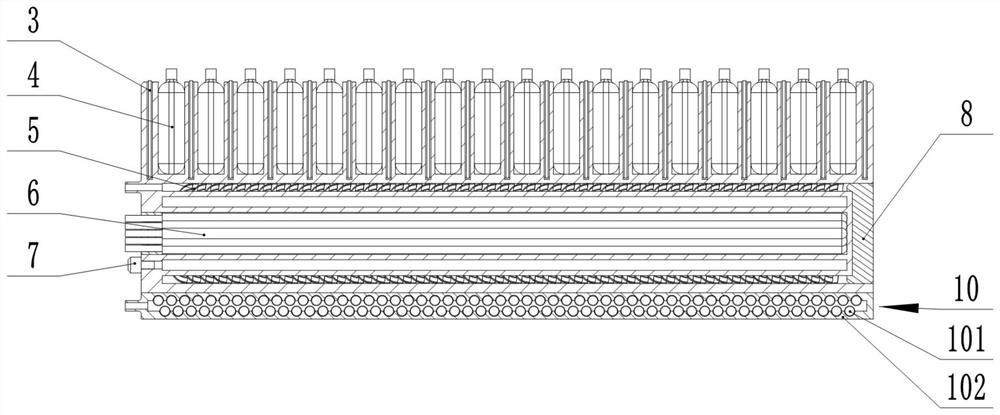
The invention discloses a multi-stage variable stiffness pneumatic soft actuator, comprising a first soft frame, an air bag, a contact-type spiral elastic variable stiffness element, a pneumatic tubular variable stiffness element, and a contact-type tooth-shaped variable stiffness module; the first soft machine There is a U-shaped groove on the top of the frame, and a plurality of independently driven airbags are fixed in the corresponding U-shaped groove in turn; the inside of the first software frame is provided with a first cavity, a second cavity, and a third cavity; the second cavity The body is located in the middle, and it is sealed and connected with the front end of the first software frame through the first end cover; the third cavity is located on the outer periphery of the second cavity, and it communicates with the outside atmosphere of the first software frame through a dust-proof vent plug; the first cavity The body is located on the periphery of the third cavity, which is sealed and connected with the rear end of the first soft frame through the second end cover; the contact type spiral elastic variable stiffness element is placed in the first cavity; multiple pneumatic tubular variable stiffness elements are evenly arranged In the second cavity; the contact tooth deformation stiffness module is fixed at the bottom of the first soft frame.
Description
Multistage Variable Stiffness Pneumatic Soft Actuator technical field [0001] The present invention relates to the technical field of soft actuators, in particular to a multi-stage variable stiffness pneumatic soft actuator. Background technique In recent years, pneumatic software actuators have the advantages of flexibility, adaptability, and safer interaction with humans. It is widely used in many fields. Especially in both the pose control and structural variable stiffness of pneumatic software actuators face, has been studied in depth. The pose control of software actuators has always been a difficult problem in the field of software actuators, which usually requires complex control algorithms. method and with precise software structure, but often only a single pose control can be achieved. From the driver's point of view, using more A modular driver, by changing the driving sequence of the driver, to realize the multi-position control of the software actuator...
Claims
Login to View More Application Information
Patent Timeline
 Patent Type & Authority Patents(China)
IPC IPC(8): B25J15/00
CPCB25J15/00Y02T50/40
Inventor 任丽丽周亮牛士超徐健佟金焦志彬
Owner JILIN UNIV
Features
- R&D
- Intellectual Property
- Life Sciences
- Materials
- Tech Scout
- Unparalleled Data Quality
- Higher Quality Content
- 60% Fewer Hallucinations
Learn More Browse by: Latest US Patents, China's latest patents, Technical Efficacy Thesaurus, Application Domain, Technology Topic, Popular Technical Reports.
© 2025 PatSnap. All rights reserved.Legal|Privacy policy|Modern Slavery Act Transparency Statement|Sitemap|About US| Contact US: help@patsnap.com


