
I-shaped steel rail calibrating and aligning device for railway construction

A steel and railway technology, applied in the field of I-beam steel rail calibration and alignment devices for railway construction, can solve the problems of position offset, poor work efficiency, high labor intensity, etc.

Active Publication Date: 2020-04-07
嘉兴尚坤科技有限公司
View PDF6 Cites 4 Cited by
  • Summary
  • Abstract
  • Description
  • Claims
  • Application Information

AI Technical Summary

Problems solved by technology

[0005] The purpose of the present invention is to provide an I-shaped steel rail calibration and alignment device for railway construction, to solve the inconvenience of fine-tuning the position of the rails proposed in the above-mentioned background technology. Cooperating between two workers seriously wastes the labor force. At the same time, the work efficiency of this fine-tuning and calibration method is poor, which seriously affects the construction progress of the rails. After calibration and alignment, it is still inconvenient to carry out displacement docking, and the problem of position deviation may occur during displacement docking

Method used


Image

  • I-shaped steel rail calibrating and aligning device for railway construction
  • I-shaped steel rail calibrating and aligning device for railway construction
  • I-shaped steel rail calibrating and aligning device for railway construction

Examples

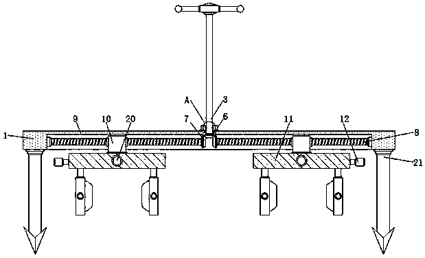
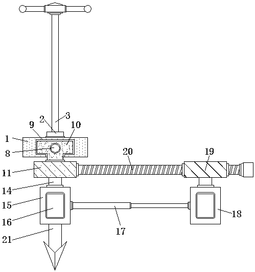
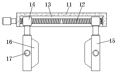

Embodiment Construction

[0025] The technical solutions in the embodiments of the present invention will be clearly and completely described below in conjunction with the accompanying drawings in the embodiments of the present invention. Obviously, the described embodiments are only a part of the embodiments of the present invention, rather than all the embodiments. Based on the embodiments of the present invention, all other embodiments obtained by those of ordinary skill in the art without creative work shall fall within the protection scope of the present invention.

[0026] See Figure 1-6 , The present invention provides a technical solution: an I-shaped steel rail alignment device for railway construction, comprising a mounting frame 1, a first bevel gear 6, a second bevel gear 7 and a first adjustment rod 8, the mounting frame 1 A mounting ring 2 is provided above, and a vertical rod 3 is provided on the inner side of the mounting ring 2, a groove 4 is provided on the surface of the vertical rod 3...


PUM


Abstract

The invention discloses an I-shaped steel rail calibrating and aligning device for railway construction. The device comprises a mounting frame, a first bevel gear, a second bevel gear and a first adjusting rod, a mounting ring is arranged above the mounting frame, a vertical rod is arranged on the inner side of the mounting ring, grooves are formed in the surface of the vertical rod and the innersurface of the mounting ring, balls are arranged on the inner sides of the grooves, the vertical rod is connected with the mounting ring through the balls, and ground nails are mounted below the mounting frame. According to the I-shaped steel rail calibrating and aligning device for railway construction, a first clamping plate below a first mounting plate is used for clamping the rail; the first clamping plate drives a second clamping plate to synchronously clamp the another rail through the telescopic rod, the first clamping plate and the second clamping plate are located at the same straightline such that the rail clamped by the first clamping plate and the rail clamped by the second clamping plate are located at the same straight line, at the moment, the two rails are aligned, and follow-up butt welding is facilitated.

Description

Technical field [0001] The invention relates to the technical field of railway construction, in particular to an I-shaped steel rail alignment device for railway construction. Background technique [0002] In recent years, with the rapid development of China's economy, the transportation between cities has become more and more convenient, especially the opening of high-speed rail. Rails, which are the basic hardware of high-speed rail tracks, are of great importance in railway construction. In order to facilitate the transportation of rails, longer rails are generally formed by splicing and welding multiple short rails in place. In order to improve the welding quality and prevent undesired displacement of the rails during the welding process, it is best to The track to be welded is limited or fixed, but most of the existing rails have the following problems during the butt installation process: [0003] 1. It is inconvenient to fine-tune the position of the rails. Most of them req...

Claims


Application Information

Patent Timeline
Patent Type & Authority Applications(China)
IPC IPC(8): E01B29/16
CPCE01B29/16
Inventor 徐亚红
Owner 嘉兴尚坤科技有限公司
Learn More