Real-time planning method for local driving route of unmanned vehicle in field environment

A driving route and route planning technology, applied in the directions of road network navigators, measuring devices, instruments, etc., can solve problems such as increasing the calculation cost, affecting the time to reach the destination, affecting the trajectory planning speed planning, etc., to optimize the distance and time cost. , the effect of improving the success rate

Active Publication Date: 2020-04-07
TSINGHUA UNIV
View PDF8 Cites 11 Cited by
  • Summary
  • Abstract
  • Description
  • Claims
  • Application Information

AI Technical Summary

Problems solved by technology

[0003] First, the effective utilization of the drivable area and the contradiction between the calculation cost
If the grid division is large, it is often marked as undrivable due to small obstacles, which wastes the space of other drivable areas in the grid, which may easily cause the problem of route planning failure; if the grid division is small, it will increase the calculation time. cost, impact planning time
[0004] Second, only the distance cost of the route is considered, and the ground properties (such as roughness, roll angle, pitch angle) in the drivable area are rarely considered, which cannot provide a better input route for the next trajectory planning, so that Affects speed planning in trajectory planning, which in turn affects time to destination
[0005] Third, there is a lack of research on re-planning methods when route planning fails under the current grid division
The existing A* algorithm does not consider that when the current map planning fails, it flexibly applies different drivable sub-area sizes to recalibrate the grid to form a planned route; nor does it consider adjusting the vehicle direction or position for real-time generation of maps and routes replanning method

Method used


Image

  • Real-time planning method for local driving route of unmanned vehicle in field environment
  • Real-time planning method for local driving route of unmanned vehicle in field environment
  • Real-time planning method for local driving route of unmanned vehicle in field environment

Examples


Embodiment Construction

[0018] The present invention will be further described below in conjunction with the accompanying drawings, constituting a part of the present invention. It should be understood that what is described here is only a specific example of the present invention, and is not intended to limit the protection scope of the present invention. Any equivalent replacement or improvement made within the spirit and principles of the present invention, etc., All should be included within the protection scope of the present invention.

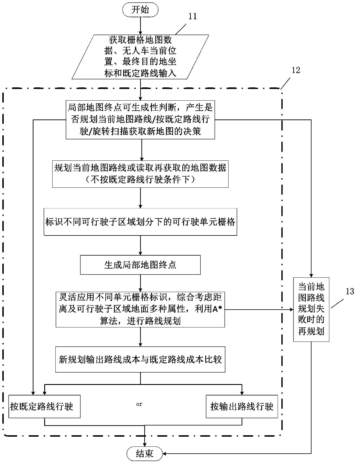
[0019] Such as figure 1 As shown, the real-time planning method for the local driving route of the unmanned vehicle under the field environment provided by the embodiment of the present invention mainly includes 3 steps:

[0020] Step 1, obtain relevant data: obtain raster map data, the current location of the unmanned vehicle, the final destination coordinates and the input of the established route;

[0021] Step 2, if the end point of the local map cannot b...


PUM


Abstract

The invention provides a real-time planning method for a local driving route of an unmanned vehicle in a field environment. The real-time planning method mainly aims at a route planning scene with a limited unmanned vehicle sensing range, real-time generation of a local map and various ground attributes in the field environment. On the basis of a real-time map in which small unit grids are divided, two types of unit grid identifiers are added by considering obstacle identifiers of surrounding grids with different area sizes by taking each unit grid as a central point; on the basis, unit gridscorresponding to different identifiers are flexibly utilized, the distance and ground attributes such as roll angles, pitch angles and roughness of drivable sub-regions are comprehensively considered,a local drivable route is planned in real time on the basis of an A * algorithm, the success rate of route planning is increased, and the distance and time cost for reaching a local end point are optimized; when the route planning fails, a route re-planning strategy is designed.

Description

technical field [0001] The invention belongs to the field of path planning, and in particular relates to a real-time planning method for a local driving route of an unmanned vehicle in a field environment. Background technique [0002] According to the grasping degree of environmental information, path planning can be divided into global path planning based on prior complete information and local path planning based on sensor information. Path planning includes two parts: route planning and driving trajectory planning. Among them, the route planning generates a route for the subject to drive based on the static map, which is used as the input of the dynamic trajectory planning; the trajectory planning determines the speed and direction of the subject to reach each actual driving trajectory point. In the wild environment, the unmanned vehicle perception system perceives the environment information in real time through the sensor, determines its own position and the distribut...

Claims


Application Information

Patent Timeline
Patent Type & Authority Applications(China)
IPC IPC(8): G01C21/34G01C21/32
CPCG01C21/3446G01C21/32
Inventor 武丹凤朱纪洪叶松发肖尧王吴凡
Owner TSINGHUA UNIV
Why Eureka
Try Eureka