Depth domain velocity modeling method for igneous rock

A velocity modeling and igneous rock technology, applied in the direction of measuring devices, instruments, scientific instruments, etc., can solve the problem of inability to accurately invert the velocity and lateral distribution characteristics of lithological bodies, and achieve fine and clear depiction and good imaging effect Effect

Inactive Publication Date: 2020-04-07
CHINA PETROLEUM & CHEM CORP +1
View PDF9 Cites 3 Cited by
  • Summary
  • Abstract
  • Description
  • Claims
  • Application Information

AI Technical Summary

Problems solved by technology

However, when special rock masses such as igneous rocks develop in the region, and the lateral distribution is only two to three hundred meters or less, especially when the lateral velocity and lithology change drastically, the conventional grid tomographic inversion method based entirely on data-driven has been unable to Accurately invert the velocity and lateral distribution characteristics of lithologic bodies

Method used


Image

  • Depth domain velocity modeling method for igneous rock
  • Depth domain velocity modeling method for igneous rock
  • Depth domain velocity modeling method for igneous rock

Examples


Embodiment Construction

[0034] The implementation of the present invention will be described in detail below in conjunction with the accompanying drawings and examples, so as to fully understand and implement the process of how to apply technical means to solve technical problems and achieve technical effects in the present invention. It should be noted that, as long as there is no conflict, each embodiment and each feature in each embodiment of the present invention can be combined with each other, and the formed technical solutions are all within the protection scope of the present invention.

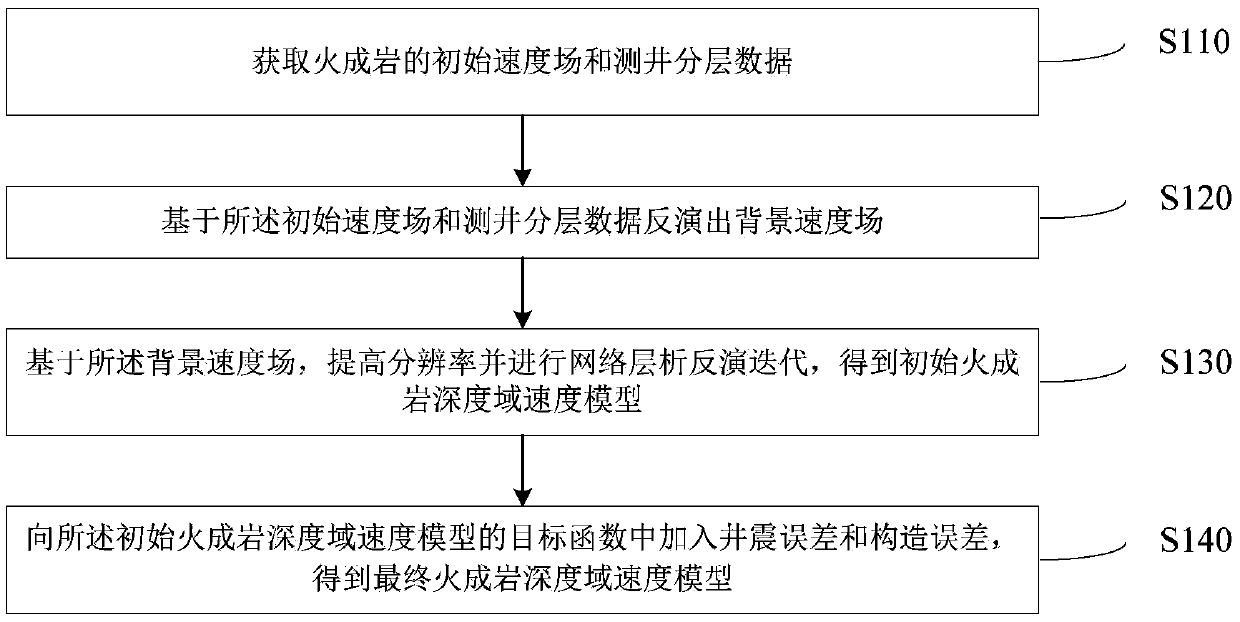
[0035] The existing data-driven grid tomographic inversion method cannot accurately describe the drastic vertical and horizontal velocity changes in the igneous rock area, and the velocity error is large, which affects the imaging of the underlying strata, and is prone to inherited false structures, false faults, etc. question. In order to solve the above problems, an embodiment of the present invention prop...


PUM


Abstract

The invention discloses a depth domain velocity modeling method for igneous rock. The method comprises: acquiring an initial velocity field and logging stratification data of the igneous rock; inverting a background velocity field based on the initial velocity field and the logging stratification data; based on the background velocity field, improving the resolution and carrying out network chromatography inversion iteration to obtain an initial igneous rock depth domain velocity model; and adding a well-to-seismic error and a construction error into the target function of the initial igneousrock depth domain speed model to obtain a final igneous rock depth domain speed model. According to the invention, the velocity model depicts igneous rock more finely, and the overall velocity changeis more reasonable. After the model is used for depth migration, the influence of igneous rock on an underlying stratum can be well eliminated, false structures and false fractures are eliminated, andthe real structural form and characteristics are recovered. And meanwhile, the tiny cracks are depicted more clearly and truly, the fracture-cavity energy is more focused, the imaging effect is better, and a good effect is achieved.

Description

technical field [0001] The invention relates to the technical field of high-precision velocity modeling in the depth domain of igneous rock development areas, in particular to a velocity modeling method in the depth domain of igneous rocks. Background technique [0002] The velocity model is a key factor affecting depth imaging. The accuracy of the event position after migration actually depends on the characteristics of the migration algorithm used and the velocity error. If the velocity error exceeds 5%, it may cause the event deformation of the underlying strata. . In the Tarim Basin, a large number of igneous rocks with drastic changes are developed in the Permian system. With the change of lithology and thickness of igneous rocks, the lateral velocity changes drastically. According to the analysis of well logs, the velocity difference of igneous rocks with different lithologies is more than 1000m / s, while the conventional grid layer Analytical velocity modeling is diff...

Claims


Application Information

Patent Timeline
Patent Type & Authority Applications(China)
IPC IPC(8): G01V1/30
CPCG01V1/303G01V2210/6222
Inventor 高厚强穆洁吕秋玲邵文潮李晶晶
Owner CHINA PETROLEUM & CHEM CORP
Why Eureka
Try Eureka