Eureka AIR delivers breakthrough ideas for toughest innovation challenges, trusted by R&D personnel around the world.

Splicing-type ceramic machining tool

A ceramic processing and splicing technology, which is applied in the direction of stone processing tools, manufacturing tools, stone processing equipment, etc., can solve the problems of unusable tools, waste of resources, and wear of cutter heads, so as to save resources, facilitate disassembly, and improve stability. Effect

Inactive Publication Date: 2020-04-14
衡阳阳光陶瓷有限公司
View PDF7 Cites 1 Cited by
  • Summary
  • Abstract
  • Description
  • Claims
  • Application Information

AI Technical Summary

Problems solved by technology

[0002] The existing ceramic processing tools are generally standard processing tools, and due to the high hardness of ceramics, the wear on the tool head is serious during processing, and when the tool head or other parts are damaged, the tool cannot be used, and the entire tool needs to be replaced. The cutter body is a waste of resources

Method used


Image

  • Splicing-type ceramic machining tool
  • Splicing-type ceramic machining tool
  • Splicing-type ceramic machining tool

Examples


Embodiment Construction

[0020] In order to facilitate the understanding of the present invention, the present invention will be described more fully below with reference to the relevant drawings, in which several embodiments of the present invention are shown, but the present invention can be realized in different forms, and is not limited to the text described On the contrary, these embodiments are provided to make the disclosure of the present invention more thorough and comprehensive.

[0021] It should be noted that when an element is said to be "fixed on" another element, it can be directly on the other element or there can be an intervening element, and when an element is said to be "connected" to another element, it can be Directly connected to another element or possibly intervening elements at the same time, the terms "vertical," "horizontal," "left," "right," and similar expressions are used herein for purposes of illustration only.

[0022] Unless otherwise defined, all technical and scien...


PUM


Abstract

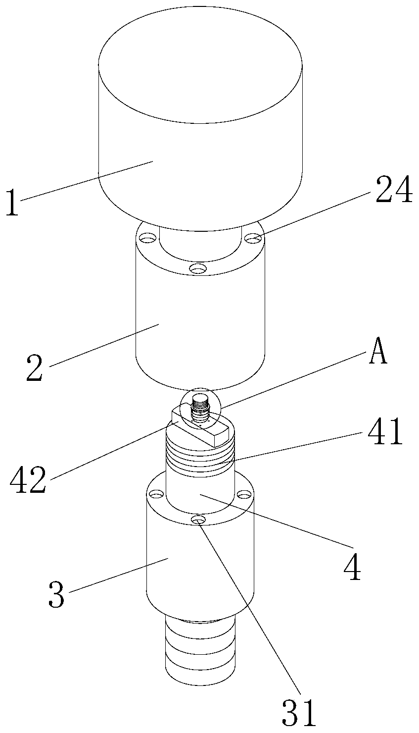
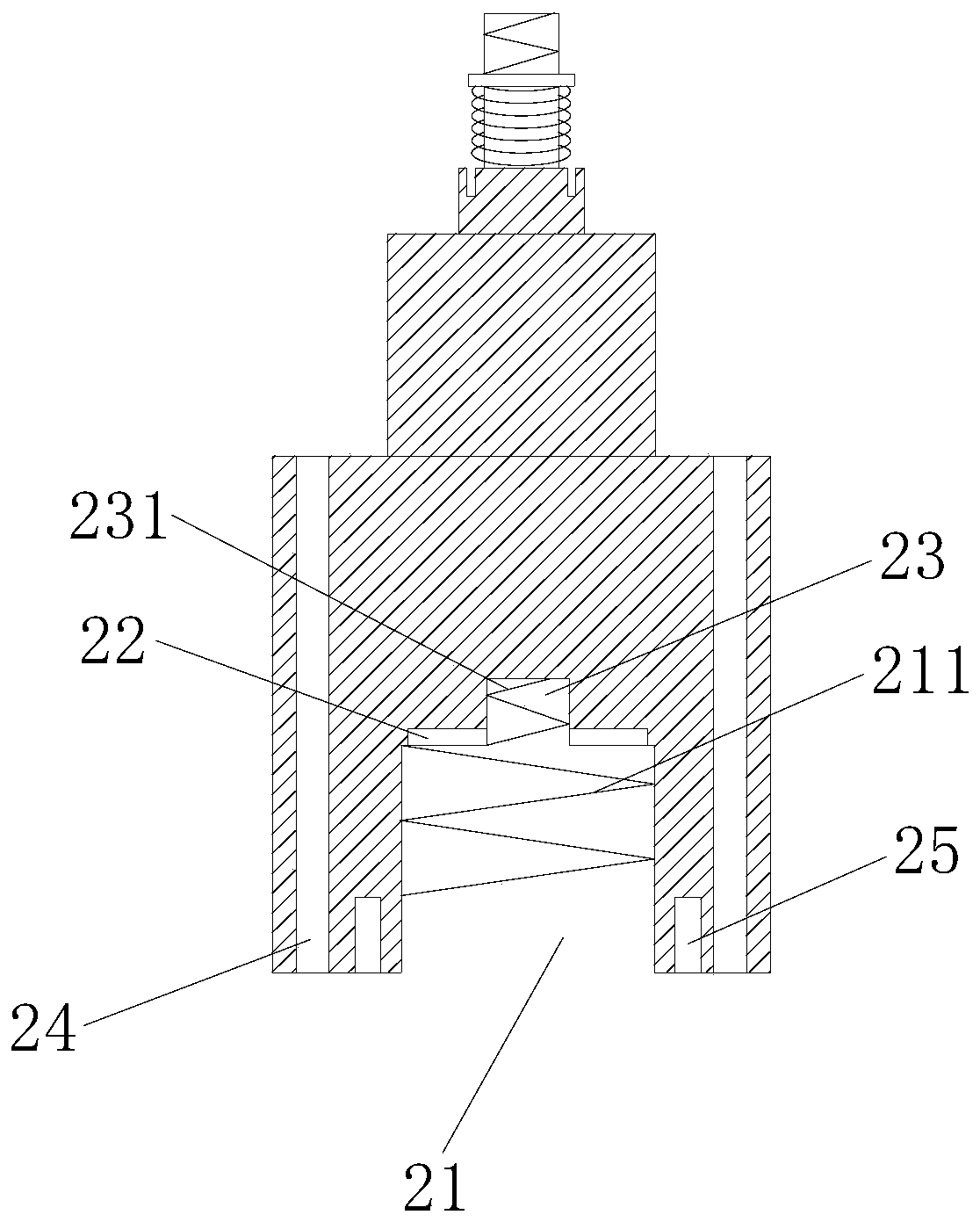
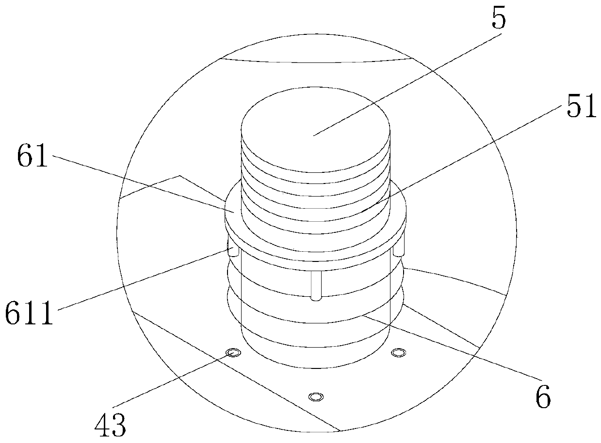
The invention provides a splicing-type ceramic machining tool. The splicing-type ceramic machining tool comprises a first tool body, a second tool body and a third tool body, a first mounting groove is formed in the bottom of each of the first tool body and the second tool body, a square clamping groove is formed in the inner top plate of each of the two first mounting grooves, a second mounting groove is formed in the center of each of the two square clamping grooves, a first mounting column is arranged at the top of each of the second tool body and the third tool body, a square clamping block is arranged at the top end of each of the two first mounting columns, a second mounting column is arranged at the top end of each of the two square clamping blocks, a plurality of second threaded holes and a plurality of third threaded holes are correspondingly formed in the top ends of the second tool body and the third tool body, and a plurality of first threaded holes are formed in the bottomof each of the first tool body and the second tool body. According to the splicing-type ceramic machining tool, through the first mounting columns, the second mounting columns, the square clamping blocks, the second threaded holes, the third threaded holes and the first threaded holes, splicing mounting of the tool is achieved, and the removal and replacement of the tool are facilitated.

Description

technical field [0001] The invention mainly relates to the technical field of ceramic processing cutters, in particular to a spliced ​​ceramic processing cutter. Background technique [0002] The existing ceramic processing tools are generally standard processing tools, and due to the high hardness of ceramics, the wear on the tool head is serious during processing, and when the tool head or other parts are damaged, the tool cannot be used, and the entire tool needs to be replaced. The cutter body is a waste of resources. Therefore, it is necessary to develop a spliced ​​ceramic processing tool. When a certain part of the tool is damaged, it can continue to be used as long as the corresponding part is replaced, which saves resources. Contents of the invention [0003] The present invention mainly provides a spliced ​​ceramic processing tool to solve the technical problems raised in the background art above. [0004] The technical solution adopted by the present invention...

Claims


Application Information

Patent Timeline
Patent Type & Authority Applications(China)
IPC IPC(8): B28D1/22
CPCB28D1/22
Inventor 阳纯文
Owner 衡阳阳光陶瓷有限公司
Why Eureka
Eureka Blog
Learn More