Plane displacement measuring device, plane motion equipment and using method thereof
A displacement measurement and plane technology, applied in the direction of measuring devices, instruments, etc., can solve the problems of difficult measurement and reset of compound motion plane displacement, and achieve the effect of short reset time and easy realization
- Summary
- Abstract
- Description
- Claims
- Application Information
AI Technical Summary
Problems solved by technology
Method used
Image
Examples
Embodiment 1
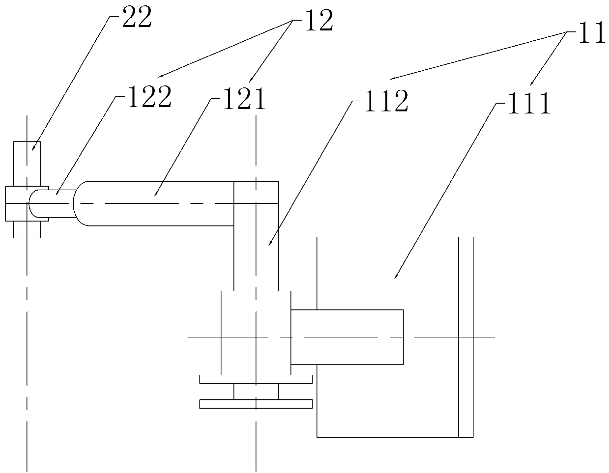
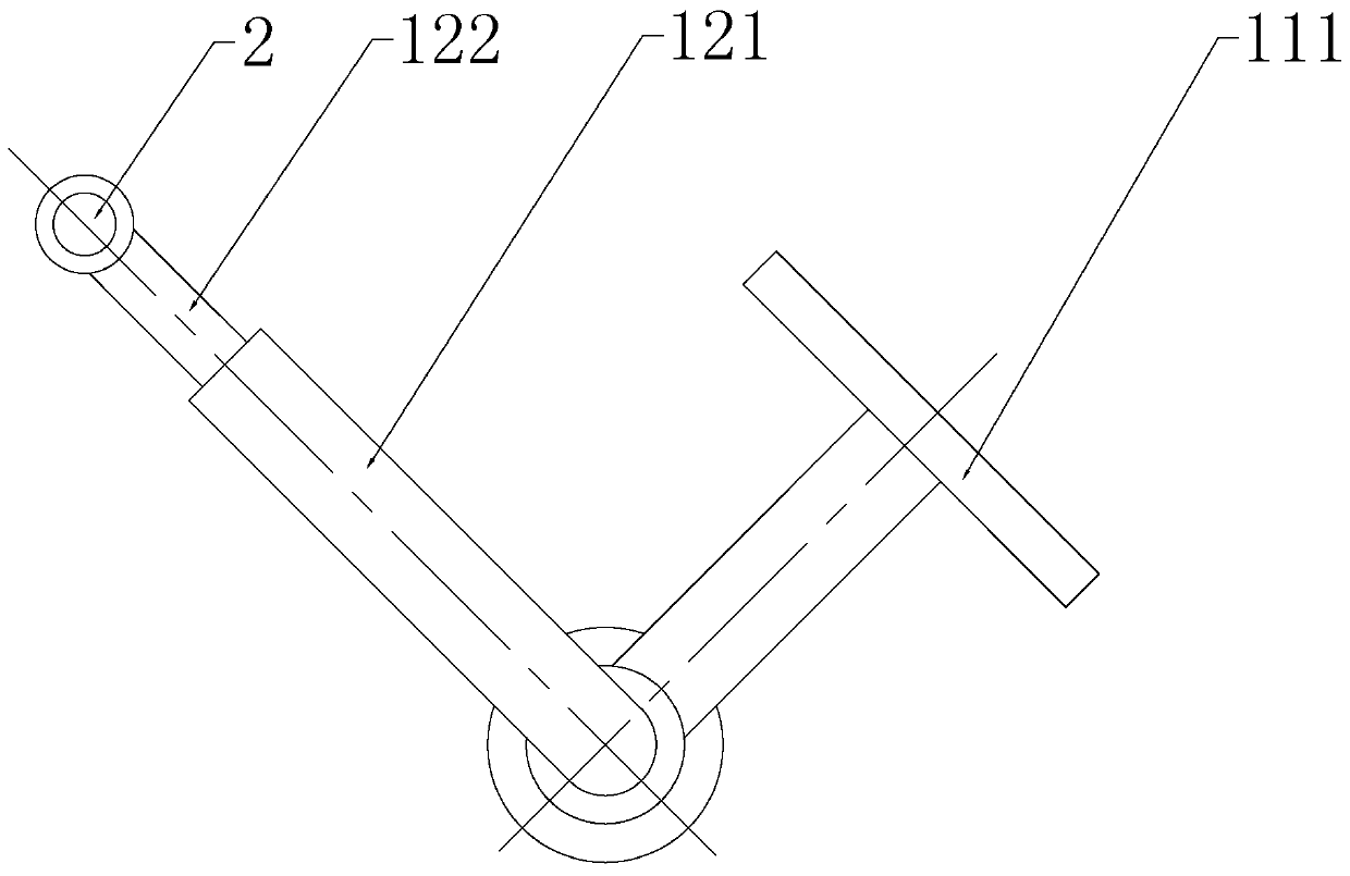
[0027] Embodiment 1: a kind of plane displacement measuring device, see Figure 1-3, used to connect the still object 21 and the animal 22, a virtual positioning axis is set on the static object 21, the animal 22 can move in the first plane perpendicular to the positioning axis, and the plane displacement measuring device includes two sets of coordinate measuring instruments, respectively the first coordinate Measuring instrument 3 and second coordinate measuring instrument 4, each group of coordinate measuring instrument all comprises angular displacement sensor (not shown), linear displacement sensor (not shown), the rotating pair 11 that rotation axis is arranged parallel to positioning axis, and moving direction is perpendicular to The moving pair 12 with the positioning axis set, the rotating pair 11 includes a first fixed piece 111 and a rotating rod 112, the first fixed piece 111 is used to keep a relatively static state with the still object, for example, the first fixe...
Embodiment 2
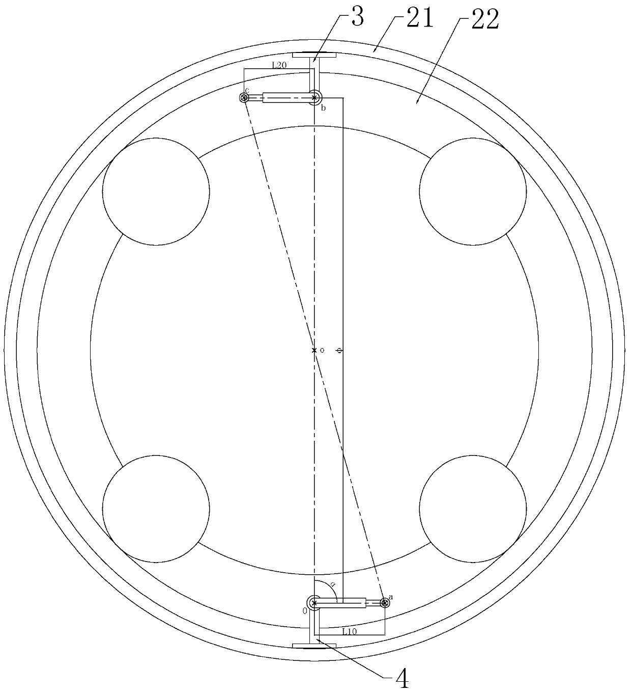
[0029] Embodiment 2: a kind of planar motion equipment, see Figure 1-3 , comprising a still life 21, an animal 22, two groups of planar movement modules (not shown) and the aforementioned planar displacement measuring device, a positioning axis is set up on the still life 21, and the animal 22 can move in a first plane perpendicular to the positioning axis, Each group of planar motion modules has a fixed part and a movable part for driving the animal 22 to move in the first plane. The fixed part and the still object 21 maintain a relatively static state, and the movable part is rotatably connected to the animal 22, and the movable part is connected to the animal 22. The rotation axis of the moving rod and the rotating shaft of the animal 22 are coaxially arranged; the moving rod of the two groups of planar displacement measuring devices and the rotating shaft of the animal 22 are respectively located on both sides of the second plane. Generally, the fixing part can be fixed o...
Embodiment 3
[0032] Embodiment 3: use the method for the planar motion equipment in embodiment 2, see Figure 3-6 , on the first plane: set ①, set a virtual tracking axis on the still object that can follow the motion of the still object, and the two sets of coordinate measuring instruments are the first coordinate measuring instrument, the second coordinate measuring instrument, and the first coordinate measuring instrument , The second coordinate measuring instrument is symmetrically installed on the animal with the positioning axis as the center, and the tracking axis coincides with the positioning axis in the initial state; set ②, the rotation axis of the second coordinate measuring instrument is the coordinate origin , the extension direction of the moving rod of the second coordinate measuring instrument is on the positive side of the X-axis, and the rotation axis of the first set of coordinate measuring instruments is located on the positive side of the Y-axis; set ③, in the first pl...
PUM
| Property | Measurement | Unit |
|---|---|---|
| Resolution | aaaaa | aaaaa |
| Resolution | aaaaa | aaaaa |
Abstract
Description
Claims
Application Information
 - R&D
- Intellectual Property
- Life Sciences
- Materials
- Tech Scout
- Unparalleled Data Quality
- Higher Quality Content
- 60% Fewer Hallucinations
Browse by: Latest US Patents, China's latest patents, Technical Efficacy Thesaurus, Application Domain, Technology Topic, Popular Technical Reports.
© 2025 PatSnap. All rights reserved.Legal|Privacy policy|Modern Slavery Act Transparency Statement|Sitemap|About US| Contact US: help@patsnap.com


