Stereoscopic rotating sound equipment
A sound and three-dimensional technology, applied in the field of stereo rotating sound, can solve the problem of not being able to feel the subwoofer, achieve good entertainment effects and increase interest
- Summary
- Abstract
- Description
- Claims
- Application Information
AI Technical Summary
Problems solved by technology
Method used
Image
Examples
specific Embodiment approach 1
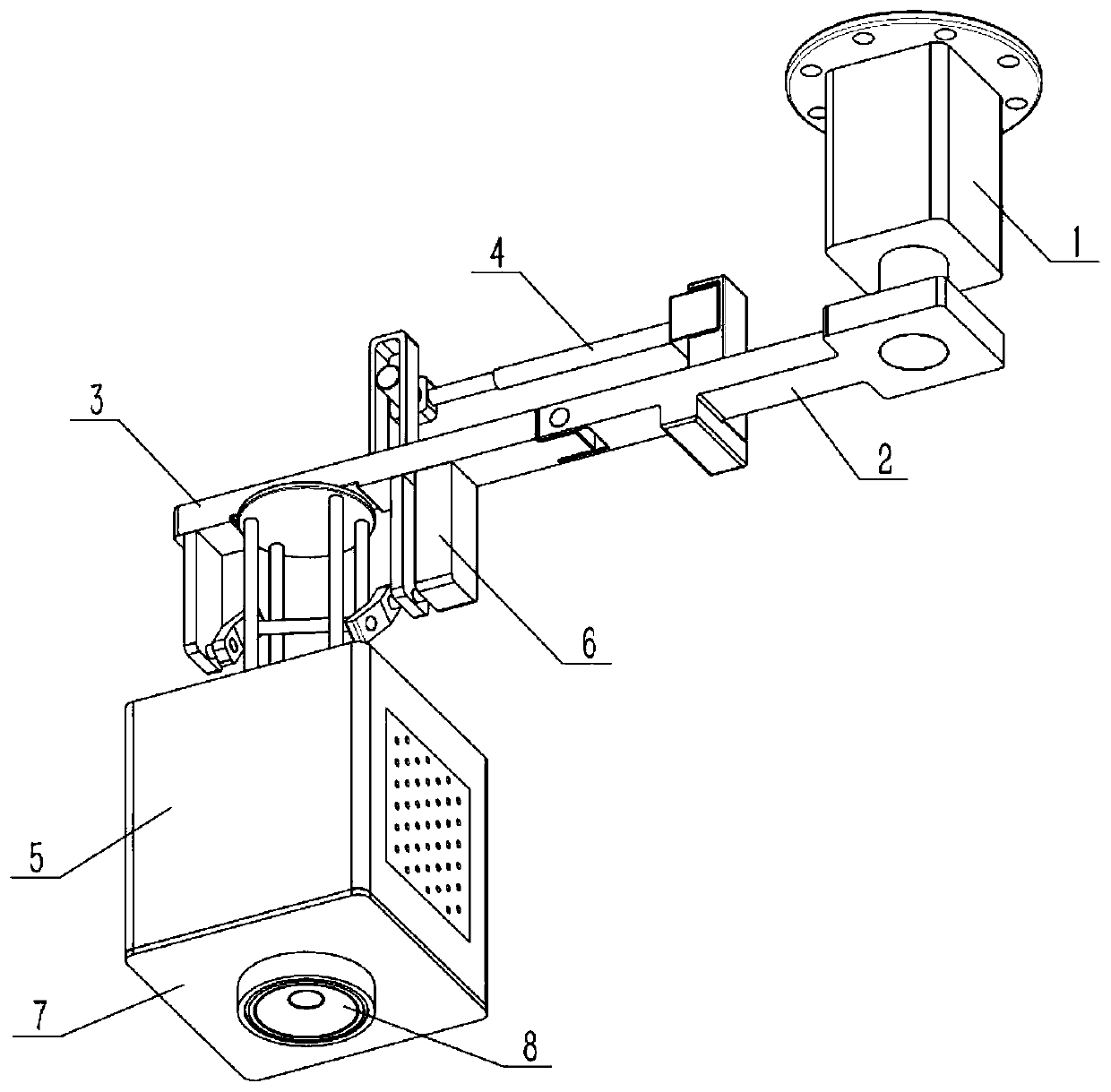
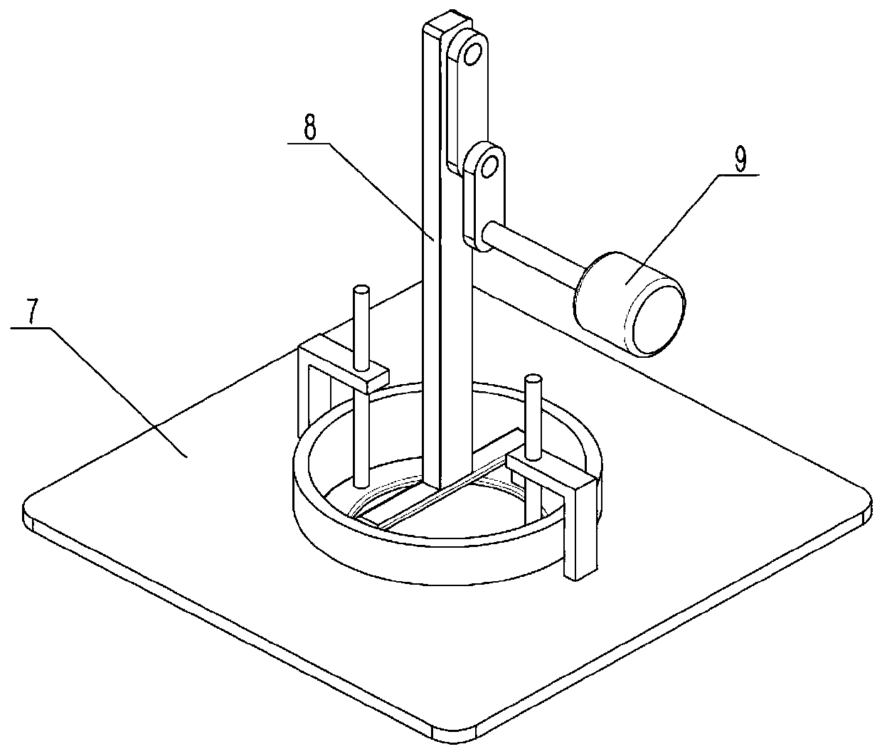
[0032] Such as Figure 1-11 As shown in the figure, a stereo rotary sound system includes a middle part 1, a main beam 2, a moving beam 3, a push-pull part 4, an audio case 5, a reciprocating trigger mechanism 6, an audio bottom case 7, a subwoofer 8 and a failure mechanism 9, The lower end of the middle part 1 is rotationally connected with the right end of the main beam 2, the left end of the main beam 2 is rotationally connected with the right end of the moving beam 3, the right end of the push-pull part 4 is fixedly connected with the main beam 2, and the left end of the push-pull part 4 is connected with a transmission. In the moving beam 3, the upper end of the sound housing 5 is rotationally connected with the left side of the moving beam 3, the reciprocating trigger mechanism 6 is connected with the left side of the lower end of the moving beam 3, the reciprocating trigger mechanism 6 is connected with the sound housing 5 through transmission, and the sound The lower e...
specific Embodiment approach 2
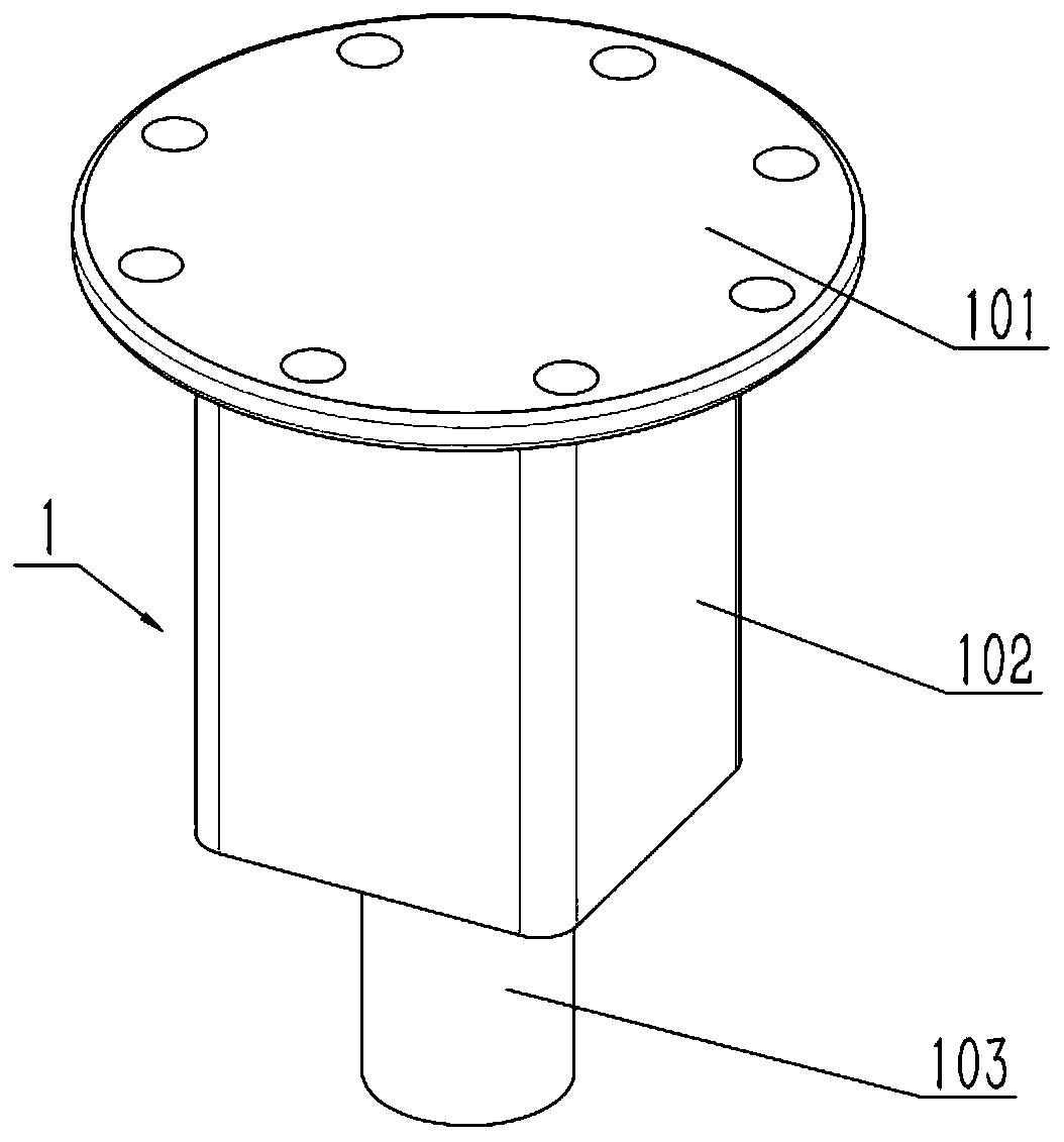
[0034] Such as Figure 1-11 As shown, the middle rotor 1 includes a fixed base 101 , a motor I 102 and a main shaft 103 , the lower end of the fixed base 101 is fixedly connected to the motor I 102 , and the output shaft of the motor I 102 is fixedly connected to the main shaft 103 . Fix the fixing seat 101 on the top, such as the roof or other shelves, and its position should be located in the center of the user's entertainment space, start the motor I102, the output shaft of the motor I102 drives the main beam body 201 to rotate, and then the main beam 2 can rotate.
specific Embodiment approach 3
[0036] Such as Figure 1-11 As shown, the main beam 2 includes a main beam body 201, a frame 202 and a short shaft 203, the middle part of the main beam body 201 is provided with a frame 202, and the left end of the main beam body 201 is fixedly connected to the short shaft 203; the main shaft 103 The lower end of the rotatably connected to the right side of the main beam body 201. The rotation of the main beam 2 can drive other parts to move synchronously with it.
PUM
 Abstract
Description
Claims
Application Information
 - R&D
- Intellectual Property
- Life Sciences
- Materials
- Tech Scout
- Unparalleled Data Quality
- Higher Quality Content
- 60% Fewer Hallucinations
Browse by: Latest US Patents, China's latest patents, Technical Efficacy Thesaurus, Application Domain, Technology Topic, Popular Technical Reports.
© 2025 PatSnap. All rights reserved.Legal|Privacy policy|Modern Slavery Act Transparency Statement|Sitemap|About US| Contact US: help@patsnap.com


