Vehicle door C-pillar parting sealing strip structure

A technology of sealing strips and seams, which is applied in the field of interior and exterior decoration of automobiles. It can solve problems such as the sealing strips falling out, the interference of the mushroom head connection structure is small, and the sealing strips are not installed in place, so as to improve the sealing performance and avoid workers complaining. The effect of saving man-hours

Active Publication Date: 2020-04-17
NINGBO GEELY AUTOMOBILE RES & DEV CO LTD +1
View PDF6 Cites 0 Cited by
  • Summary
  • Abstract
  • Description
  • Claims
  • Application Information

AI Technical Summary

Problems solved by technology

[0002] In order to make the door C-pillar high-gloss injection molding trim panel (hereinafter referred to as the trim panel) visually flush with the D-pillar trim panel, the trim panel needs to be designed to be pressed on the water cut outside the door, which will cause the trim panel to be in line with the sheet metal and rear door The combination of multiple structures such as corner windows restricts the structure of the trim itself
On this basis, the production process of this type of decorative panel will further restrict the installation of the C-pillar split sealing strip (hereinafter referred to as the sealing strip), making it difficult to install the sealing strip
[0003] At present, the common fixing method of the sealing strip is that the sealing strip is clamped and fixed with the square hole structure on the decorative plate through the mushroom head connection structure, but this kind of fixing method is easy to cause the sealing strip to not be installed in place or the sealing strip to fall out after installation when the space is insufficient. problem, and the mushroom head connection structure itself has a small amount of clamping interference, and it is difficult to install it in place during installation

Method used


Image

  • Vehicle door C-pillar parting sealing strip structure
  • Vehicle door C-pillar parting sealing strip structure
  • Vehicle door C-pillar parting sealing strip structure

Examples


Embodiment Construction

[0023] In order to further illustrate the technical means and functions adopted by the present invention to achieve the intended purpose of the invention, the present invention will be described in detail below in conjunction with the accompanying drawings and preferred embodiments.

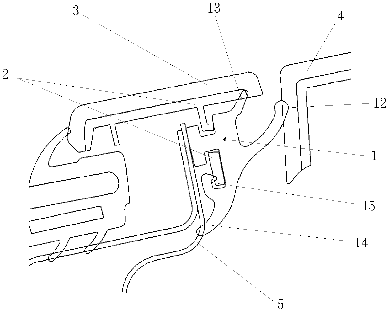
[0024] The car door C-pillar split seal structure of the present invention is located between the C-pillar high-gloss trim panel 3 and the D-pillar high-gloss trim panel 4 in the vehicle body length direction, and is located inside the C-pillar high-gloss trim panel 3 in the vehicle body width direction.

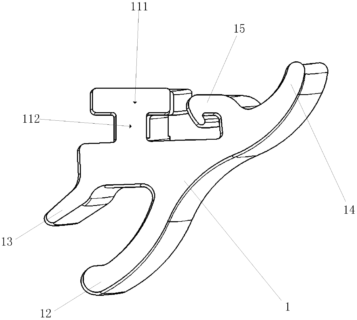
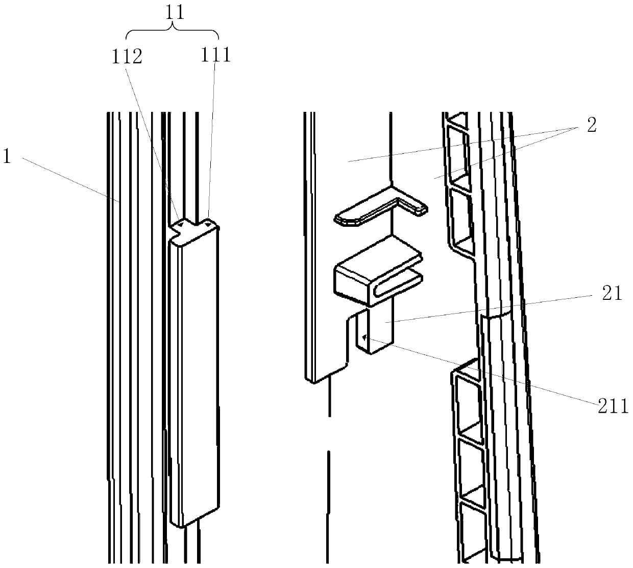
[0025] see Figure 1 to Figure 2 , the car door C-pillar split sealing strip structure of the present invention includes a sealing strip 1 and a decorative panel 2, the decorative panel 2 is located on the inner side of the C-pillar high-gloss decorative panel 3 and is offset against the C-pillar high-gloss decorative panel 3, and the sealing strip 1 is in three directions Respectively offset w...


PUM


Abstract

The invention discloses a vehicle door C-pillar parting sealing strip structure comprising a sealing strip and decorative plate. The sealing strip is arranged between a C-column highlight decorative plate and a D-column highlight decorative plate in the length direction of a vehicle body and the sealing strip and the decorative plate are arranged on the inner side of the C-column highlight decorative plate in the width direction of the vehicle body; the decorative plate is attached to the inner side of the C-column highlight decorative plate; the sealing strip is connected to the decorative plate in a clamped mode; and the sealing strip is abutted against a vehicle door metal plate, the C-column highlight decorative plate and the D-column highlight decorative plate at the same time. According to the invention, the clamping part with the wide part and the narrow part is arranged on the sealing strip, so that the sealing strip is firmly assembled on the decoration strip; the risk that the sealing strip is disengaged from the decoration plate is reduced while the sealing performance of the sealing strip is improved; and the disengagement problem of the C-column sealing strip is solved.

Description

technical field [0001] The invention relates to the technical field of interior and exterior decoration of automobiles, in particular to a C-pillar seam sealing strip structure of a car door. Background technique [0002] In order to make the door C-pillar high-gloss injection molding trim panel (hereinafter referred to as the trim panel) visually flush with the D-pillar trim panel, the trim panel needs to be designed to be pressed on the water cut outside the door, which will cause the trim panel to be in line with the sheet metal and rear door The combination of multiple structures such as corner windows restricts the structure of the trim itself. On this basis, the production process of this type of decorative panel will further restrict the installation of the C-pillar joint sealing strip (hereinafter referred to as the sealing strip), making it difficult to install the sealing strip. [0003] At present, the common fixing method of the sealing strip is that the sealing...

Claims


Application Information

Patent Timeline
IPC IPC(8): B60R13/04B60J10/84B60J10/30
CPCB60R13/043B60J10/30B60J10/84
Inventor 刘民国
Owner NINGBO GEELY AUTOMOBILE RES & DEV CO LTD
Why Eureka
Try Eureka