Cold beam structure and cold beam air conditioning system

A technology of chilled beams and nozzles, applied in the field of air-conditioning equipment, can solve problems such as obstruction of air flow velocity and inability to meet the air supply requirements of tall spaces

Pending Publication Date: 2020-04-17
GREE ELECTRIC APPLIANCES INC OF ZHUHAI
View PDF1 Cites 2 Cited by
  • Summary
  • Abstract
  • Description
  • Claims
  • Application Information

AI Technical Summary

Problems solved by technology

[0003] The existing problem of this kind of active chilled beam is that the airflow organization in the chilled beam structure mainly relies on the air gu

Method used


Image

  • Cold beam structure and cold beam air conditioning system
  • Cold beam structure and cold beam air conditioning system
  • Cold beam structure and cold beam air conditioning system

Examples


Example

[0030] The first embodiment of chilled beam structure

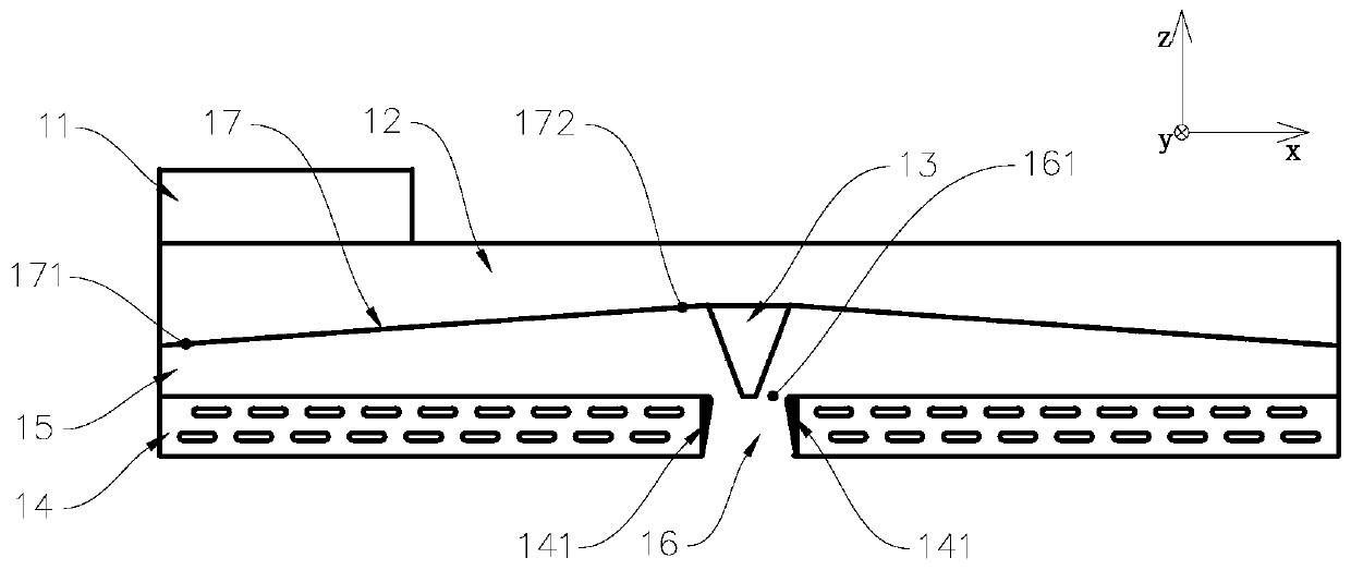
[0031] see figure 1 , figure 1 It is a schematic structural diagram of the cross-section in the extension direction of the first embodiment of the chilled beam structure of the present invention. In the space coordinate system established in the figure, the x-axis direction is the width direction of the chilled beam structure (the first horizontal direction), the y-axis direction is the length direction of the chilled beam structure (the second horizontal direction), and the z-axis direction is the height direction ( vertical). The chilled beam air conditioning system provided by the present invention has a chilled beam structure installed on the top wall of the floor, the top of the chilled beam structure has an access air duct 11 connected to the air conditioner, and the access air duct 11 is used to access primary air. The lower part of the access air duct 11 is the static pressure chamber 12, and the outer surface ...


PUM


Abstract

The invention provides a cold beam structure and a cold beam air conditioning system. The cold beam structure comprises a static pressure chamber, heat exchangers and a nozzle. The cold beam structureis provided with a partition plate which shield the static pressure chamber from the bottom, the nozzle is connected to the partition plate downwards, the nozzle communicates with the static pressurechamber, the heat exchangers are arranged below the partition plate, an airflow channel is formed between the heat exchangers and the partition plate, and the airflow channel is extended in the firsthorizontal direction. An air outlet channel is formed between the two heat exchangers and located below the nozzle, and the air outlet cannel runs through in the vertical direction. The airflow channel and the air outlet channel communicate at the position of the nozzle. The cold beam air conditioning system comprises the cold beam structure. Indoor air enters the airflow channel from the heat exchangers to become secondary air, and the secondary air is mixed with the primary air sent by the nozzle under the Venturi effect and then passes through the air outlet channel with a short stroke tobecome strong downward jet flow so as to reach the bottom of the space sufficiently, and therefore the cold beam structure is suitable for high and large spaces.

Description

technical field [0001] The invention relates to the technical field of air conditioning equipment, in particular to a chilled beam structure and a chilled beam air conditioning system. Background technique [0002] The Chinese invention patent application with the application number CN201711260128.1 discloses an active chilled beam and a chilled beam air conditioning system. The air outlet and the air inlet are provided with heat exchange tube coils; the two sides of the air inlet are provided with air outlets, the static pressure chamber has nozzles facing the air outlet, and the housing is provided with an air outlet channel connected with the air outlet, and the air outlet is provided with Rotatable wind deflector. [0003] The existing problem of this kind of active chilled beam is that the airflow organization in the chilled beam structure mainly relies on the air guide vane to realize the attached air supply, and the flow rate of the air supply is hindered, which cann...

Claims


Application Information

Patent Timeline
IPC IPC(8): F24F1/0014F24F1/0047F24F1/0063F24F13/06F24F13/22
CPCF24F1/0014F24F1/0047F24F1/0063F24F13/06F24F13/22F24F2013/221
Inventor 王子平黄玉优谢文利
Owner GREE ELECTRIC APPLIANCES INC OF ZHUHAI
Why Eureka
Try Eureka