A method for testing dynamic mechanical properties of rock at high temperature and a heating furnace used therewith

A technology of dynamic mechanics and testing methods, which is applied in the direction of applying repeated force/pulsation force to test the strength of materials, measuring devices, scientific instruments, etc., and can solve the problems of not being able to use strain gauges, affecting waveforms, and affecting the accuracy of rock dynamic mechanical test results, etc. problem, to achieve the effect of saving experimental cost, ensuring accuracy and simple method

Active Publication Date: 2021-04-02
CENT SOUTH UNIV
View PDF6 Cites 0 Cited by
  • Summary
  • Abstract
  • Description
  • Claims
  • Application Information

AI Technical Summary

Problems solved by technology

In the second method, although there will be a temperature gradient on the rod, the data directly obtained by the strain gauge cannot be used to study the mechanical properties of the sample, but in this case the SHPB device with a simple structure is retained
[0005] For the study of the dynamic mechanical properties of rock materials at high temperatures, although some scholars have carried out related work, most of them are studying the dynamic compression properties of rocks, and lack of dynamic stretching, fracture and larger-sized rocks. The research on the mechanical properties of the sample is mainly due to the technical limitations of the original real-time heating furnace device
In dynamic tensile or fracture tests, in order to obtain reliable experimental results, the rod and the sample must be heated at the same time, so a temperature gradient will inevitably occur on the rod, and the elastic modulus of the rod will change at high temperatures, which will cause Affecting the waveform will ultimately affect the accuracy of rock dynamic mechanical test results

Method used


Image

  • A method for testing dynamic mechanical properties of rock at high temperature and a heating furnace used therewith
  • A method for testing dynamic mechanical properties of rock at high temperature and a heating furnace used therewith
  • A method for testing dynamic mechanical properties of rock at high temperature and a heating furnace used therewith

Examples


Embodiment Construction

[0053] The following will clearly and completely describe the technical solutions in the embodiments of the present invention with reference to the accompanying drawings in the embodiments of the present invention. Obviously, the described embodiments are only some, not all, embodiments of the present invention. Based on the embodiments of the present invention, all other embodiments obtained by persons of ordinary skill in the art without creative efforts fall within the protection scope of the present invention.

[0054] A method for testing rock dynamic mechanical properties at high temperatures, comprising the steps of:

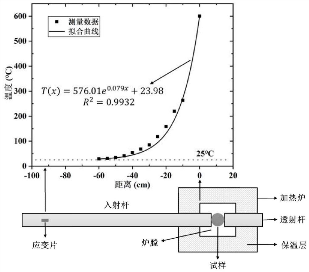
[0055] S1. Install the incident rod and transmission rod of the SHPB experimental system coaxially on the through holes on both sides of the heating furnace, and extend to the heating furnace to clamp the sample, keeping the sample at the center of the furnace; the incident rod and the transmission rod The rods are made of Cr40 alloy.

[0056] S2. Paste ...


PUM


Abstract

The invention discloses a method for testing the dynamic mechanical property of rock at high temperature, which comprises the following steps of coaxially mounting an incident bar and a transmission bar of an SHPB (split Hopkinson pressure bar) experimental system on through holes on two sides of a heating furnace respectively, and extending into the heating furnace to clamp a sample; adhering strain gauges to the incident bar and the transmission bar, wherein the strain gauges on the incident bar and the transmission bar are symmetrically arranged on two sides of the sample; starting a heating furnace, and heating the rock sample to a set temperature; launching a bullet, conducting an SHPB experiment, and measuring incident wave, reflected wave and transmitted wave data through a strain gauge; correcting the measured incident wave, reflected wave and transmitted wave data; and analyzing the deformation and damage conditions of the sample material by utilizing the corrected incident wave, reflected wave and transmitted wave to obtain accurate dynamic mechanical property data of the sample at high temperature.

Description

technical field [0001] The invention belongs to the technical field of rock dynamic mechanical properties testing, and in particular relates to a method for testing rock dynamic mechanical properties at high temperature and a heating furnace for supporting use. Background technique [0002] The split Hopkinson bar (split Hopkinson pressure bar), referred to as SHPB, is named after John Hopkinson and his son Bertram Hopkinson in 1872 who invented a pressure bar that can obtain a force-time curve that generates a dynamic load through impact. Later, the system underwent a series of improvements and developments. In 1948, Davies improved the measurement technology by using the electrical measurement method. In 1949, Kolsky developed the separation rod system. In 1954, Krafft used strain gauges to measure stress waves and added a Punching to generate repeatable shock stress waves, Lindholm combined previous improvements in 1964 to design an upgraded version of the SHPB system, wh...

Claims


Application Information

Patent Timeline
Patent Type & Authority Patents(China)
IPC IPC(8): G01N3/34G01N3/62
CPCG01N3/34G01N3/62G01N2203/0067G01N2203/0075G01N2203/0226G01N2203/0647
Inventor 尹土兵王超吴攸吴炳强
Owner CENT SOUTH UNIV
Why Eureka
Try Eureka