Predicting and reducing noise in vibratory meter

A meter and noise technology, applied in the direction of specific gravity measurement, measuring device, mass flow measuring device, etc., can solve problems such as intermodulation distortion

Active Publication Date: 2020-04-17
MICRO MOTION INC
View PDF10 Cites 2 Cited by
  • Summary
  • Abstract
  • Description
  • Claims
  • Application Information

AI Technical Summary

Problems solved by technology

However, the multi-tone approach may introduce intermodulation distortion

Method used


Image

  • Predicting and reducing noise in vibratory meter
  • Predicting and reducing noise in vibratory meter
  • Predicting and reducing noise in vibratory meter

Examples


Embodiment Construction

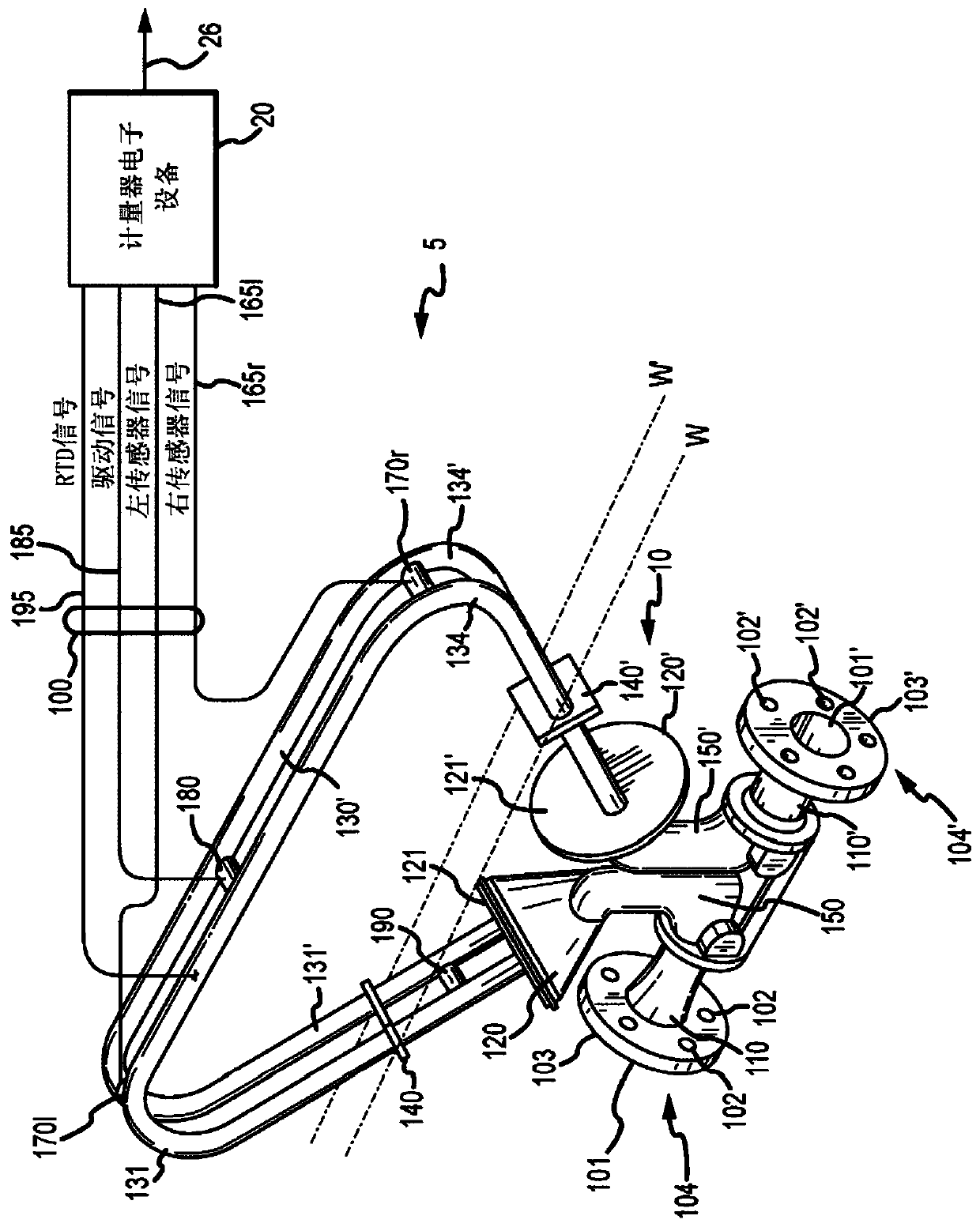
[0052] Figure 1 to Figure 17 And the following description depicts specific examples of the best mode of implementation that teach those skilled in the art how to make and use the implementations that predict and reduce noise in vibrating meters. For the purpose of teaching inventive principles, some conventional aspects have been simplified or omitted. Those skilled in the art will appreciate variations from these examples that fall within the scope of the description. Those skilled in the art will appreciate that the features described below can be combined in various ways to form multiple variations that predict and reduce noise in vibrating meters. As a result, the embodiments described below are not limited to the specific examples described below, but only by the claims and their equivalents.

[0053] Noise can be reduced by generating a compensation signal. The compensation signal may be an inverse weighted signal applied to the drive signal provided to the sensor a...


PUM


Abstract

A vibratory meter (5, 1600) configured to predict and reduce noise in the vibratory meter (5, 1600). The vibratory meter (5, 1600) includes a sensor assembly (10, 1610) and a meter electronics (20, 1620) in communication with the sensor assembly (10, 1610). The meter electronics (20, 1620) is configured to provide a drive signal to a sensor assembly (10, 1610), receive a sensor signal from the sensor assembly (10, 1610) having one or more components, and generate a signal to be applied to one of the sensor signal and the drive signal to compensate for the one or more components.

Description

technical field [0001] The embodiments described below relate to noise in sensor signals in vibrating meters, and more particularly, to predicting and reducing noise in vibrating meters. Background technique [0002] Vibrating meters such as, for example, Coriolis mass flow meters, liquid density meters, gas density meters, liquid viscometers, gas / liquid pycnometers, gas / liquid relative density meters and gas molecular weight meters are generally known And used to measure the properties of the fluid. Typically, a meter includes a sensor assembly and an electronics section. The material within the sensor assembly can be flowing or stationary. Each type of sensor can have unique characteristics that must be considered for optimal performance of the meter. For example, some sensors may require the tube equipment to vibrate at a specific level of displacement. Other sensor component types may require special compensation algorithms. [0003] Meter electronics typically incl...

Claims


Application Information

Patent Timeline
Patent Type & Authority Applications(China)
IPC IPC(8): G01F1/84G01F25/00
CPCG01N9/002G01F1/8431G01F1/8436G01F25/10
Inventor 马修·约瑟夫·伦辛克里斯托弗·乔治·拉森
Owner MICRO MOTION INC
Why Eureka
Try Eureka