Air centrifugal atomizing nozzle

A centrifugal atomization and nozzle technology, used in the field of iron and steel metallurgy, can solve the problems of atomization cone atomization particle size, atomization speed adjustment, small droplet dropping, uneven liquid particles, etc. The effect of deep layer and small hardness gradient

Pending Publication Date: 2020-04-21
JIANGSU GONGCHANG ROLL
View PDF0 Cites 1 Cited by
  • Summary
  • Abstract
  • Description
  • Claims
  • Application Information

AI Technical Summary

Problems solved by technology

The disadvantages of the atomizing nozzles used in the existing impact atomization technology are that the particles produced by the impact atomization are relatively large, and the liquid particles are relatively uneven. Small droplets will drip while spraying liquid, and it is difficult to correct The scope of the atomization cone, the size of the atomized particles, the atomization speed, etc. can be adjusted

Method used


Image

  • Air centrifugal atomizing nozzle

Examples


Embodiment 1

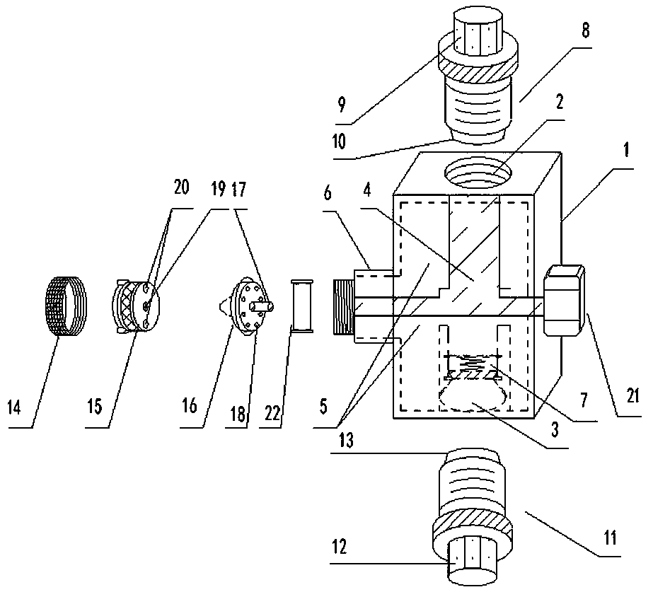
[0020] Such as figure 1 The shown air centrifugal atomizing nozzle includes a nozzle body 1, the nozzle body 1 is a square column, and a liquid inlet 2 and a gas inlet 3 are respectively provided on a pair of parallel surfaces of the nozzle body 1, and the inside of the nozzle body 1 is provided with There are liquid chamber 4 and gas chamber 5 independent of each other, one end of the liquid chamber 4 is connected to the liquid inlet 2, one end of the gas chamber 5 is connected to the gas inlet 3, and the other end of the liquid chamber 4 is connected to the gas chamber 5 The other end of the two is commonly connected to the nozzle seat 6, and a one-way valve 7 controlled by a spring is provided in the gas chamber 5 near the gas inlet; the liquid inlet 2 is provided with a hydraulic insert 8, and the hydraulic insert 8 includes Hydraulic adjustment cap 9 and liquid pipe 10; the gas inlet 3 is provided with a gas insert 11, and the gas insert 11 includes an air pressure adjust...

Embodiment 2

[0022] Referring to Example 1, an optimized design of a conical airflow hole, the central periphery of the fluid nozzle is uniformly distributed with 8 conical airflow holes along the circumferential direction, and the conical airflow holes are offset at an angle of 15° in the same direction, forming a centrifugal airflow.


PUM


Abstract

The invention discloses an air centrifugal atomizing nozzle. The air centrifugal atomizing nozzle comprises a nozzle body, a liquid cavity and a gas cavity which are independent of each other are formed in the nozzle body, the liquid cavity is connected with a liquid inlet and a spray head seat, the gas cavity is connected with a gas inlet and a spray head seat, and a one-way valve is arranged atthe position, close to the gas inlet, in the gas cavity; a hydraulic insert is arranged at the liquid inlet; the gas inlet is provided with a gas insert; an external thread is arranged in the periphery of the spray head seat; a positioning check ring with an internal thread is arranged to fix an air cap and the fluid nozzle into the nozzle seat in sequence; a fluid center pipe is arranged in the center of the fluid nozzle, and a plurality of conical airflow holes are formed in the periphery of the center. One end of the fluid center pipe is connected with the liquid cavity, the other end of the fluid center pipe is connected to a hollow liquid outlet formed in the center of the air cap, airflow holes are distributed in the air cap and located at the two sides of the liquid outlet, and a gap exists between the air cap and the fluid nozzle to form the gas cavity. The nozzle is suitable for workpiece surface water quenching, and has the advantages of large operation area, deep hardening layer and low hardness gradient.

Description

technical field [0001] The invention belongs to the field of iron and steel metallurgy, and in particular relates to an air centrifugal atomizing nozzle used for water quenching the surface of workpieces in the metallurgical process. Background technique [0002] At home and abroad, atomization technology is widely used in environmental protection, chemical industry, steel, metallurgy, electronics, cement, food, papermaking, printing, agriculture and animal husbandry and other industries. [0003] In the prior art, the atomization technology includes the impact atomization technology. The disadvantages of the atomizing nozzles used in the existing impact atomization technology are that the particles produced by the impact atomization are relatively large, and the liquid particles are relatively uneven. Small droplets will drip while spraying liquid, and it is difficult to correct The scope of the atomization cone, the size of the atomized particles, and the atomization spee...

Claims


Application Information

Patent Timeline
Patent Type & Authority Applications(China)
IPC IPC(8): B05B7/06B05B7/12B05B3/10B05B12/08B05B12/16
CPCB05B3/1014B05B7/066B05B7/12B05B12/082B05B12/16
Inventor 陈先锋李军徐进郑一帆
Owner JIANGSU GONGCHANG ROLL
Why Eureka
Try Eureka