Electro-proportional pressure continuously-adjustable hydraulic motor/pump

A hydraulic motor and electric proportional technology, applied in the direction of servo motor components, fluid pressure actuation devices, fluid pressure actuation system components, etc., can solve the problems of reducing energy recovery efficiency, motor failure, large throttling or overflow loss, etc. , to achieve the effect of simple structure

Active Publication Date: 2018-01-26
TAIYUAN UNIV OF TECH
View PDF7 Cites 17 Cited by
  • Summary
  • Abstract
  • Description
  • Claims
  • Application Information

AI Technical Summary

Problems solved by technology

[0003] As a power element in the hydraulic system, the proportional constant pressure pump can control the outlet pressure to keep constant, but it can only realize the function of the hydraulic pump and cannot be used as a motor. In construction machinery, the gravitational potential energy and For the kinetic energy in the braking process of the slewing mechanism, the existing electrical recovery methods are flow control or displacement control. In order to establish the torque balance at the beginning of the recovery, it is necessary to use the auxiliary method of throttling or overflow, which reduces the efficiency of energy recovery.
Such as the application of patent publication number CN105008729A, it is proposed to connect a relief valve or a throttle valve in series before recovering the variable motor to reduce the braking impact and improve the controllability of the rotary braking and the lowering of the boom. throttling or overflow losses

Method used


Image

  • Electro-proportional pressure continuously-adjustable hydraulic motor/pump
  • Electro-proportional pressure continuously-adjustable hydraulic motor/pump
  • Electro-proportional pressure continuously-adjustable hydraulic motor/pump

Examples


Embodiment Construction

[0031] The specific embodiments of the present invention will be further described below in conjunction with the accompanying drawings.

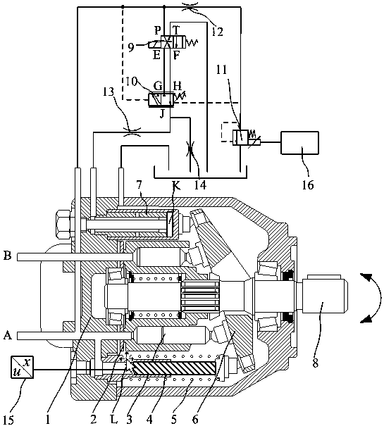
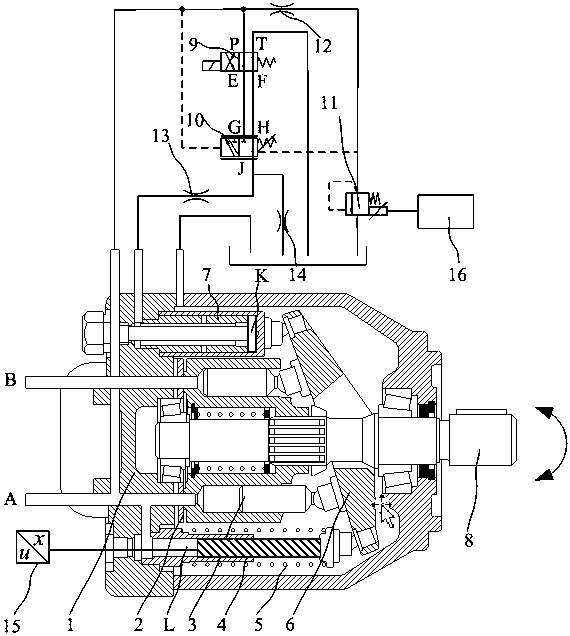
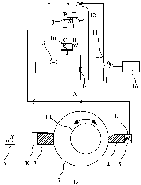
[0032] as attached figure 1 As shown, an electric proportional pressure continuously adjustable hydraulic motor / pump includes a cylinder assembly 1, a flow plate 2, a plunger assembly 3, a first variable piston 4, a swash plate return spring 5, a swash plate 6, a second The variable piston 7 and the main shaft 8 are characterized in that an electromagnetic switching valve 9, a main control pressure valve 10, a pilot proportional relief valve 11, a first damping hole 12, a second damping hole 13, a third damping hole 14, and a displacement sensor are added. 15 and a proportional amplifier 16, the oil port A of the hydraulic motor / pump communicates with the oil port P of the electromagnetic switching valve 9, the oil inlet of the first damping hole 12 and the left control chamber of the main control pressure valve 10, and the first damping hol...


PUM


Abstract

An electro-proportional pressure continuously-adjustable hydraulic motor / pump is characterized in that an electromagnetic switching valve, a main-control pressure valve, a pilot proportional valve, damping holes, a displacement sensor and a proportional amplifier are additionally arranged on the basis of a variable plunger motor or a variable plunger pump. According to the hydraulic motor / pump provided by the invention, the functions of a hydraulic motor and a hydraulic pump are integrated; the working conditions of the hydraulic pump and the hydraulic motor can be switched over by controllingthe diversion of the electromagnetic switching valve and a spindle of the hydraulic motor / pump; the pressure of an oil inlet / outlet of the hydraulic motor / pump can be adjusted in real time by adjusting the set value of the pilot proportional valve and changing the swing angle of a swash plate, thereby continuously adjusting the inlet / outlet pressure of the hydraulic motor / pump; the hydraulic motor / pump is simple in structure and convenient to control, and can be combined with a motor / power generator into an electrical recycling system; accordingly, the energy of engineering machinery and thelike can be recycled without throttling loss, and the impact and vibration generated at the beginning of recycling can be inhibited; and the hydraulic motor / pump has great application prospects and popularization value.

Description

technical field [0001] The invention relates to a hydraulic motor / pump for continuous regulation, in particular to a hydraulic motor / pump for continuous regulation of electric proportional pressure, belonging to hydraulic power and actuators for electric proportional control. Background technique [0002] The plunger motor and plunger pump are one of the key components in the hydraulic transmission system. They have the advantages of compact structure, high efficiency and high pressure, and are widely used in construction machinery, mining machinery and other equipment. [0003] As a power element in the hydraulic system, the proportional constant pressure pump can control the outlet pressure to keep constant, but it can only realize the function of the hydraulic pump and cannot be used as a motor. In construction machinery, the gravitational potential energy and For the kinetic energy in the braking process of the slewing mechanism, the existing electrical recovery methods ...

Claims


Application Information

Patent Timeline
Patent Type & Authority Applications(China)
IPC IPC(8): F15B13/02F15B15/17F15B21/14F04B1/24F04B1/30
Inventor 权龙郝云晓权仲翊赵斌王鹤
Owner TAIYUAN UNIV OF TECH
Why Eureka
Try Eureka