
Protection device for reducing scratches on surface of PCB

A protection device and PCB board technology, which is applied in the direction of transportation and packaging, containers to prevent mechanical damage, containers, etc., can solve the problems of scratches on the surface of PCB boards, collisions, and PCB boards are easy to collide with each other, so as to ensure quality and avoid displacement Effect

Pending Publication Date: 2020-04-21
AOSHIKANG TECH CO LTD
View PDF7 Cites 3 Cited by
  • Summary
  • Abstract
  • Description
  • Claims
  • Application Information

AI Technical Summary

Problems solved by technology

[0003] Traditionally, when the PCB boards are transported, the PCB boards are easy to collide with each other, and the PCB boards are also easy to collide with the inner wall of the housing, which is likely to cause scratches on the surface of the PCB board

Method used


Image

  • Protection device for reducing scratches on surface of PCB
  • Protection device for reducing scratches on surface of PCB
  • Protection device for reducing scratches on surface of PCB

Examples


no. 1 example

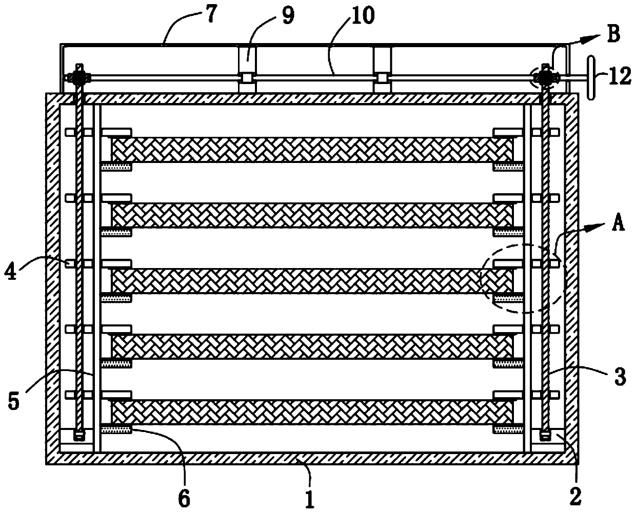
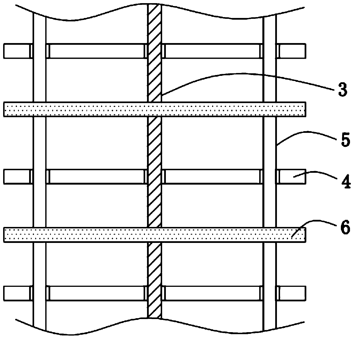
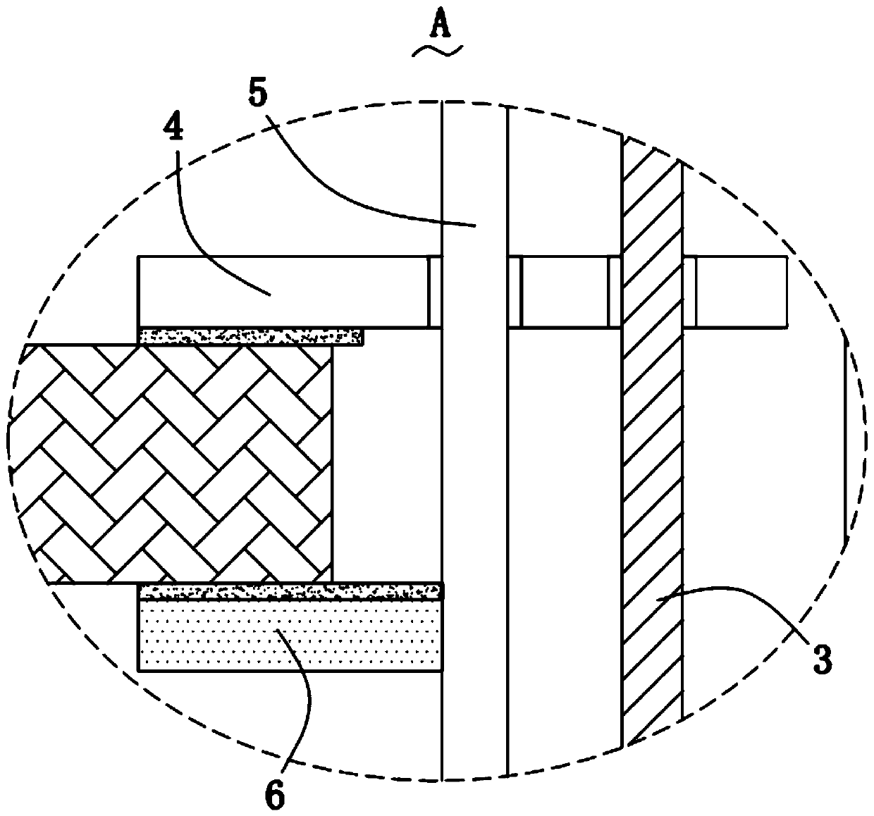
[0025] Please refer to Figure 1-6 , in the first embodiment of the present invention, the protective device for reducing scratches on the surface of the PCB includes: a transport box 1; two fixing blocks 2, and the two fixing blocks 2 are symmetrically fixed on the inner wall of the transport box 1 Two screw mandrels 3, the two said screw mandrels 3 are respectively rotated and mounted on the corresponding fixed blocks 2; a plurality of clamping plates 4, and a plurality of said clamping plates 4 are threadedly mounted on the corresponding fixed blocks 2 on the screw rod 3; four fixed rods 5, all of which are fixedly installed in the transport box 1, and the fixed rods 5 are slidably connected with the corresponding clamping plates 4; multiple positioning Plate 6, a plurality of positioning plates 6 are fixedly installed on the two fixed rods 5 respectively; installation cover 7, the installation cover 7 is fixedly installed on the top of the transport box 1, and the two scre...

no. 2 example

[0038] Based on the protection device for reducing scratches on the surface of the PCB provided by the first embodiment of the present application, the second embodiment of the present application proposes another protection device for reducing scratches on the surface of the PCB. The second embodiment is only a preferred mode of the first embodiment, and the implementation of the second embodiment will not affect the independent implementation of the first embodiment.

[0039] The second embodiment of the present invention will be further described below in conjunction with the drawings and implementation methods.

[0040] Please refer to Figure 7-8 The protection device for reducing scratches on the surface of the PCB board also includes a moving mechanism, which is fixedly installed on the bottom of the transport box 1, and the moving mechanism includes a bottom plate 14, four supporting legs 15 and four supporting columns 16, The bottom plate 14 is fixedly mounted on the...


PUM


Abstract

The invention provides a protection device for reducing scratches on the surface of a PCB. The protection device for reducing the scratches on the surface of the PCB comprises a transport case, two fixing blocks, two screw rods, a plurality of clamping plates, four fixed rods, a plurality of positioning plates and an installation cover. The two fixing blocks are symmetrically and fixedly arrangedon the inner wall of the transport case, the two screw rods are respectively and rotatably installed on the corresponding fixing blocks, the multiple clamping plates are correspondingly arranged on the corresponding screw rods in a threaded mode, the four fixed rods are correspondingly and fixedly installed in the transport case, the fixed rods are slidably connected with the corresponding clamping plates, the multiple positioning plates are respectively and fixedly installed on the two fixed rods, and the installation cover is fixedly installed on the top of the transport base. The protectiondevice for reducing the scratches on the surface of the PCB has the advantages of simple operation, convenient fixing of the PCB and guarantee of the quality of the PCB.

Description

technical field [0001] The invention relates to the technical field of PCB board protection equipment, in particular to a protection device for reducing scratches on the surface of a PCB board. Background technique [0002] Printed circuit boards, also known as printed circuit boards, printed circuit boards, or printed boards for short, use insulating boards as the base material, cut to a certain size, with at least one conductive pattern attached to it, and holes (such as component holes, Fastening holes, metallized holes, etc.), used to replace the chassis of the previous installation of electronic components, and to realize the interconnection between electronic components. [0003] Traditionally, when the PCB boards are transported, the PCB boards are likely to collide with each other, and the PCB boards are also likely to collide with the inner wall of the housing, which may easily cause scratches on the surface of the PCB board. [0004] Therefore, it is necessary to ...

Claims


Application Information

Patent Timeline
Patent Type & Authority Applications(China)
IPC IPC(8): B65D25/10B65D81/05B65D25/24
CPCB65D25/10B65D81/05B65D25/24
Inventor 王晓春
Owner AOSHIKANG TECH CO LTD
Learn More