Slider locking device and push-pull assembly with slider locking device

A locking device and locking component technology are applied in the directions of the fastening device of the wing fan, the suspension device of the wing fan, the wing fan component, etc., which can solve the problems of hidden safety hazards, damage to the opening, sliding of the sliding parts, etc.

Active Publication Date: 2021-06-04
DONGFENG MOTOR CORP HUBEI
View PDF6 Cites 1 Cited by
  • Summary
  • Abstract
  • Description
  • Claims
  • Application Information

AI Technical Summary

Problems solved by technology

[0003] Existing sliding parts are often unable to achieve locking, or rely on their own gravity or static friction to achieve a stop at a certain position. However, this kind of stop basically cannot achieve locking. Once other external forces (impact, shaking, bumps, etc.) , will cause the sliding part to slide, destroy the current opening, and even cause other potential safety hazards

Method used


Image

  • Slider locking device and push-pull assembly with slider locking device
  • Slider locking device and push-pull assembly with slider locking device
  • Slider locking device and push-pull assembly with slider locking device

Examples


Embodiment Construction

[0023] The present invention will be further described in detail below in conjunction with the accompanying drawings and specific embodiments.

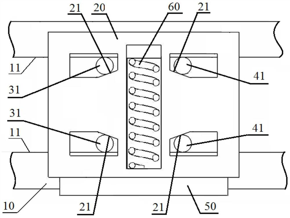
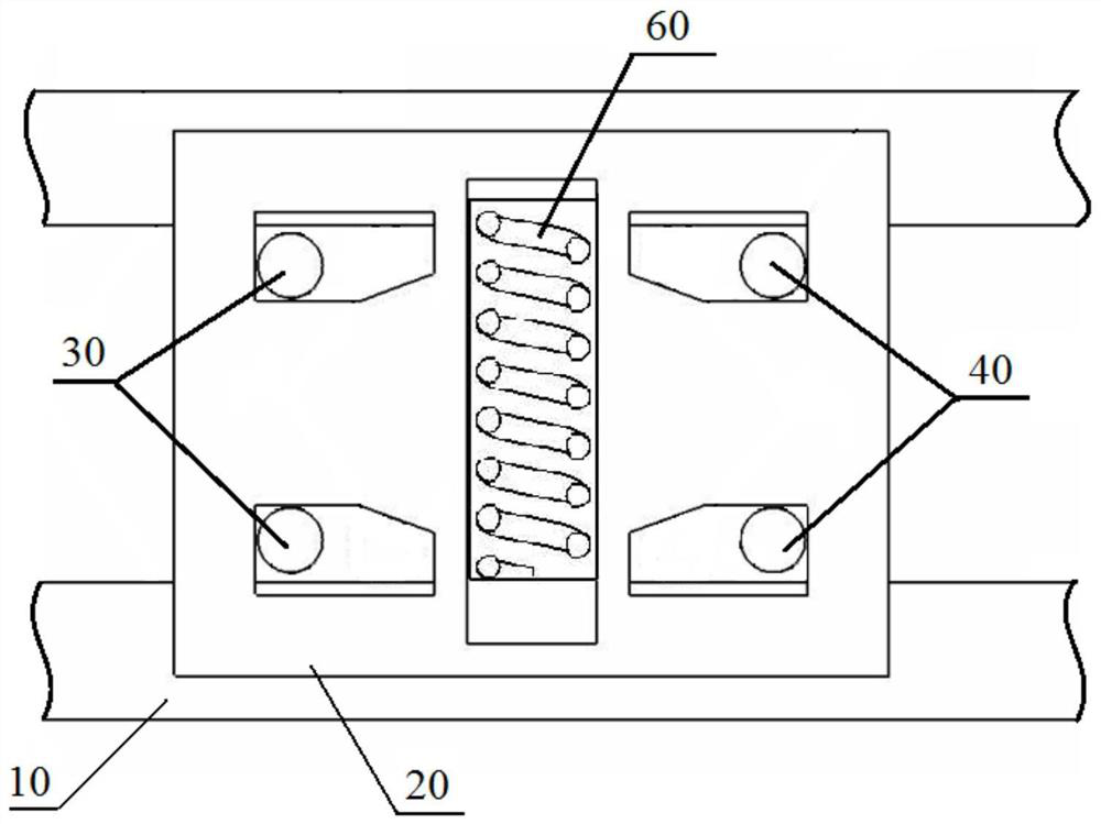
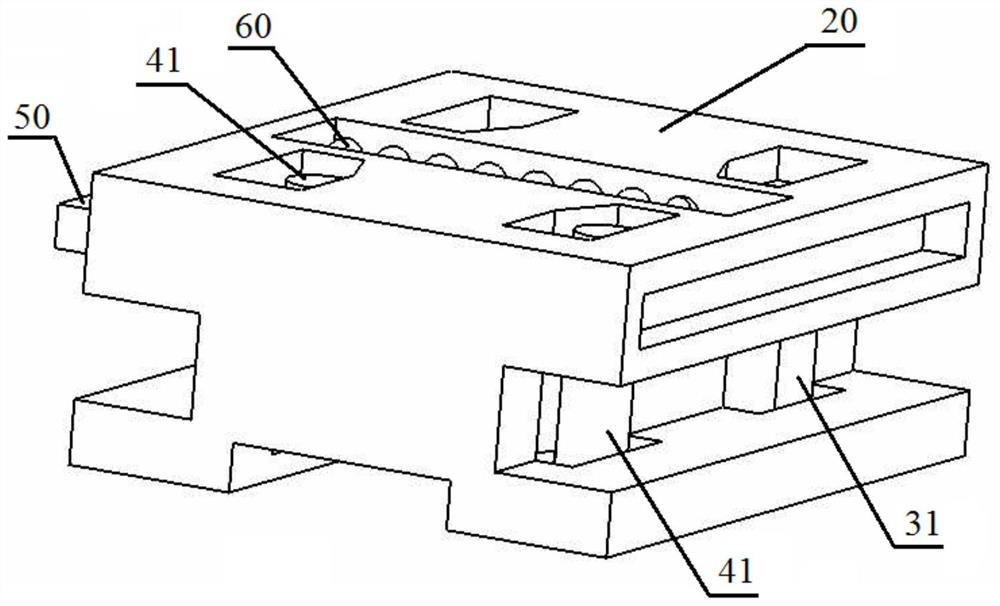
[0024] Please refer to figure 1 , figure 2 with image 3 , the slider locking device of the preferred embodiment of the present invention includes a guide rail 10, a slider 20, a locking member, a position plate 50 and an elastic member 60, the slider 20 can be slidably placed in the guide rail 10 along the guide rail 10, and locked The components are arranged in the slider 20 along the sliding direction perpendicular to the slider 20, the position plate 50 is arranged in the slider 20 relative to the slider 20 to move in another direction perpendicular to the sliding direction, and the elastic member 60 is installed on the slider 20. Together with the position plate 50 and provide the position plate 50 with an elastic restoring force for clamping the locking component between the guide rail 10 and the slider 20 perpendicular to th...


PUM


Abstract

The invention discloses a slider locking device and a push-pull assembly using the slider locking device. The slider locking device includes a guide rail, a slider, a locking part, a position plate and an elastic part. The slider can slide along the guide rail. Placed in the guide rail, the locking part is set in the slider along the sliding direction perpendicular to the sliding direction, the position plate is set in the slider so that it can move relative to the slider along the other direction perpendicular to the sliding direction, and the elastic part is installed on the slider It is connected with the position plate and provided to the position plate to clamp the locking component between the guide rail and the slide block perpendicular to the sliding direction. In the present invention, a locking part for providing locking and a position plate for controlling the position of the locking part are arranged on the two relative moving parts of the guide rail and the slider, and the position of the locking part is controlled by the position board so that the slider can be locked or Unlocking, so as to realize the function that the sliders can lock each other at any position on the guide rail; its structure is simple, easy to operate, and can be widely used in the scene of sliding movement.

Description

technical field [0001] The invention relates to the technical field of sliding parts, in particular to a sliding block locking device and a push-pull assembly using the sliding block locking device. Background technique [0002] For some sliding parts with relative motion, it is often expected that the relative motion can be reliably locked at any position, so as to use this locking to achieve the purposes of ensuring safety, convenient use, and reliable locking. For example, sliding doors, sliding windows, etc. need to be locked at different openings for ventilation and other needs. [0003] Existing sliding parts are often unable to achieve locking, or rely on their own gravity or static friction to achieve a stop at a certain position. However, this kind of stop basically cannot achieve locking. Once other external forces (impact, shaking, bumps, etc.) , causing the sliding part to slide, destroying the current opening, and even creating other potential safety hazards. ...

Claims


Application Information

Patent Timeline
Patent Type & Authority Patents(China)
IPC IPC(8): E05C17/60
CPCE05C17/60
Inventor 赵凤云李鹏陈利王希阁孙龙飞
Owner DONGFENG MOTOR CORP HUBEI
Why Eureka
Try Eureka