Eureka AIR delivers breakthrough ideas for toughest innovation challenges, trusted by R&D personnel around the world.

Boarding power take-off control system, method and engineering machinery

A technology for control systems and power take-offs, applied in control devices, vehicle components, auxiliary drive devices, etc., can solve problems such as broken power take-off gears, avoid power shortages, eliminate potential safety hazards, and solve insufficient power for boarding Effect

Active Publication Date: 2020-03-24
ZOOMLION HEAVY IND CO LTD
View PDF6 Cites 3 Cited by
  • Summary
  • Abstract
  • Description
  • Claims
  • Application Information

AI Technical Summary

Problems solved by technology

Since the power take-off of the chassis transfer case does not have a clutch, during the above power take-off process, the gearbox may lock the forward gear or close the clutch when the reverse gear is closed, and then close the control valve of the power take-off device of the chassis transfer case, resulting in Power take-off gear broken

Method used


Image

  • Boarding power take-off control system, method and engineering machinery
  • Boarding power take-off control system, method and engineering machinery
  • Boarding power take-off control system, method and engineering machinery

Examples


Embodiment Construction

[0038] Specific embodiments of the present invention will be described in detail below in conjunction with the accompanying drawings. It should be understood that the specific embodiments described here are only used to illustrate and explain the present invention, not to limit the present invention.

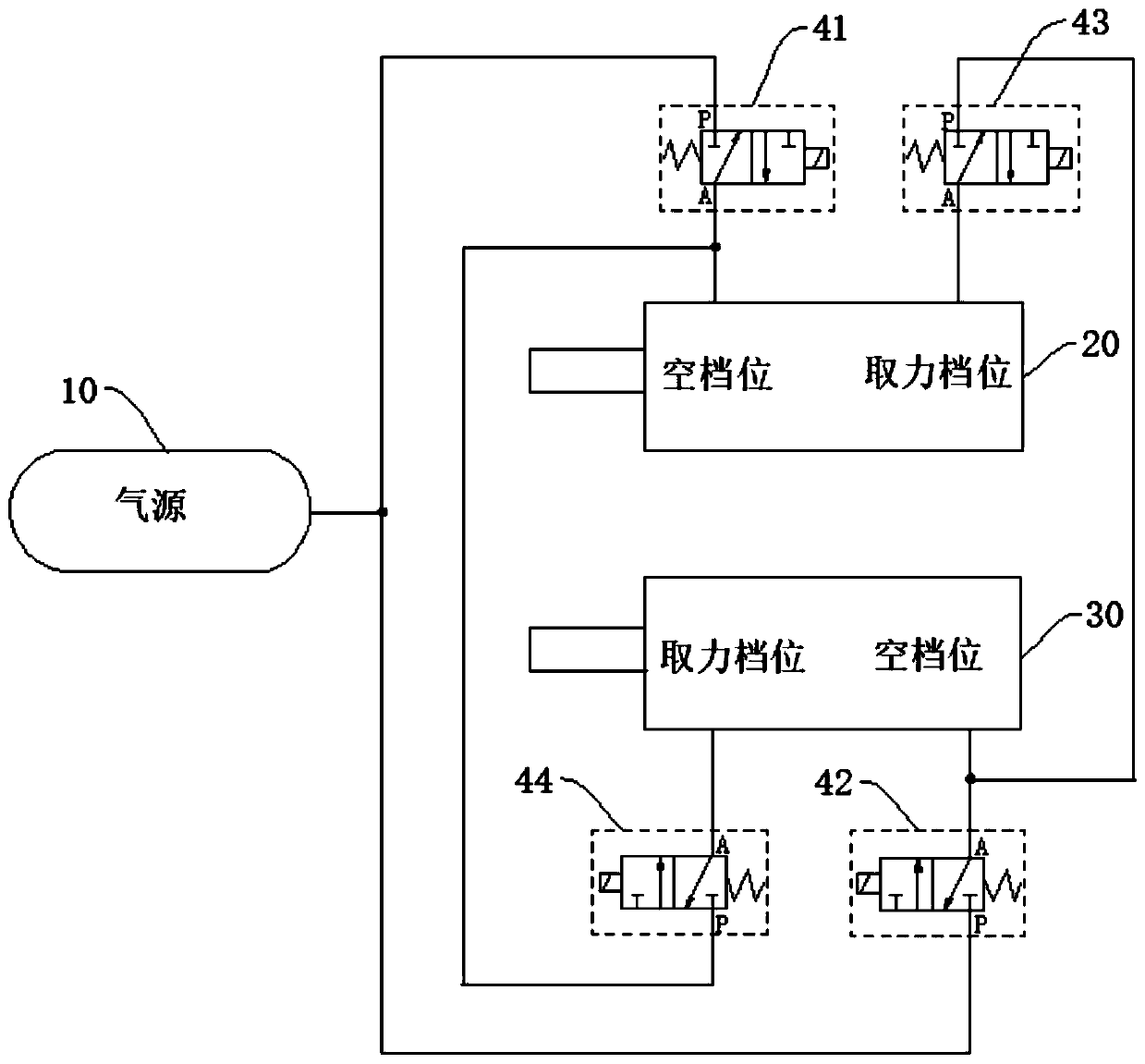
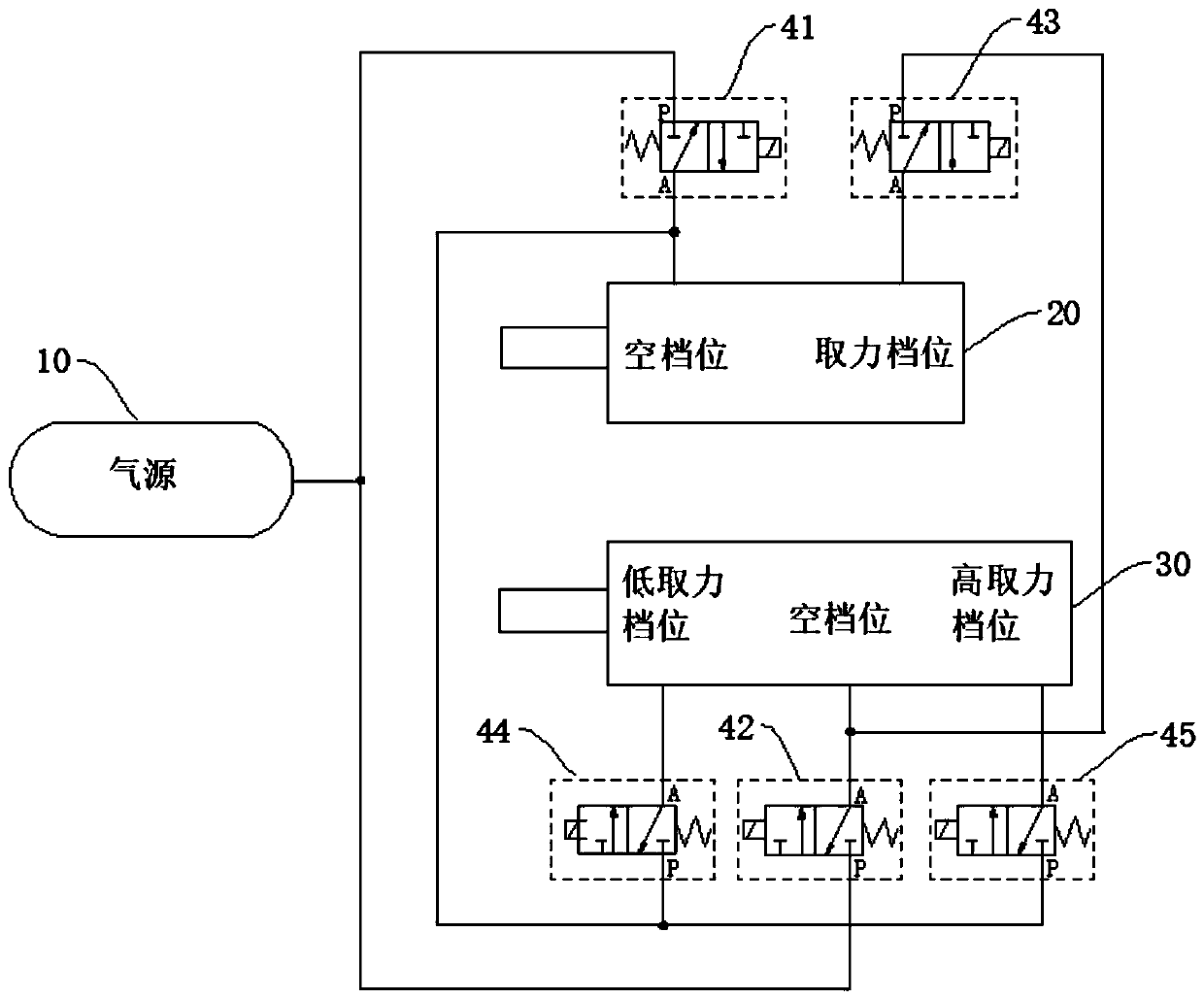
[0039] figure 1 It is a schematic structural diagram of a boarding power take-off control system provided by an embodiment of the present invention. Such as figure 1 As shown, the boarding power take-off control system provided by this embodiment includes the boarding power take-off 20, the transfer case shift cylinder 30 and the solenoid valve group, and the boarding power take-off 20 and the transfer case shifting cylinder 30 all include neutral gear and power take-off gear. The solenoid valve group includes a first two-position three-way solenoid valve 41 , a second two-position three-way solenoid valve 42 , a third two-position three-way solenoid valve 43 and a fourth two...


PUM


Abstract

The invention relates to the field of engineering machinery, and discloses a boarding power take-off control system, a method and engineering machinery. The boarding power take-off control system comprises a boarding power take-off device, a transfer case gear shifting air cylinder and an electromagnetic valve set. The boarding power takeoff and the transfer case gear shifting air cylinder each comprise a neutral gear and a power take-off gear, and the electromagnetic valve set controls the ventilation state of the boarding power takeoff and the transfer case gear shifting air cylinder so thatthe neutral gear of one of the boarding power takeoff and the transfer case gear shifting air cylinder can be locked with the power take-off gear of the other of the boarding power takeoff and the transfer case gear shifting air cylinder. When one of the transfer case gear shifting air cylinder and the boarding power takeoff is in a neutral position state, the other one can enter a non-neutral-position working state. When the power take-off operation is carried out, the chassis transmission system cannot output power; when the chassis transmission system outputs driving power, the boarding cannot take off the power; and the problem of insufficient power caused by extra power consumption is solved.

Description

technical field [0001] The invention relates to the field of engineering machinery, in particular to a control system for taking power from a boarding vehicle, a method for controlling power taking from a boarding vehicle, and a construction machine. Background technique [0002] Existing engineering machinery, such as truck cranes, are a kind of crane mounted on an ordinary car chassis or a special car chassis. The driving cab is set separately from the lifting control room. Keep your legs steady. The chassis performance of the truck crane is equivalent to that of a truck with the same total weight, which meets the technical requirements of road vehicles, so it can pass on various roads. Large-tonnage truck cranes with a lifting capacity of more than 90 tons often have two engines, one under the chassis engine, used to drive, and its emissions meet the relevant regulations on road emissions; one on-board engine, used to drive the operating mechanism, its emissions Complie...

Claims


Application Information

Patent Timeline
Patent Type & Authority Applications(China)
IPC IPC(8): B60K25/00
CPCB60K25/00
Inventor 冯科喜沈苏李元珍方杰平
Owner ZOOMLION HEAVY IND CO LTD
Why Eureka
Eureka Blog
Learn More