Electro-mechanical brake actuator with internal power electronics unit and energy store

A technology of power electronic devices and actuators, applied in the field of electromechanical brake actuators, which can solve the problems of no longer ensuring the availability of rail vehicles, failure of braking action, disadvantageous functional safety and system availability

Active Publication Date: 2020-04-21
KNORR BREMSE SYST FUR SCHIENENFAHRZEUGE GMBH
View PDF9 Cites 0 Cited by
  • Summary
  • Abstract
  • Description
  • Claims
  • Application Information

AI Technical Summary

Problems solved by technology

The inventors of the present invention have found that this is disadvantageous in the context of functional safety and system availability
A failure of the external energy store or the central supply line before branching off to the actuator results in a failure of the braking action (“dangerous failure”) in the active ac

Method used


Image

  • Electro-mechanical brake actuator with internal power electronics unit and energy store
  • Electro-mechanical brake actuator with internal power electronics unit and energy store
  • Electro-mechanical brake actuator with internal power electronics unit and energy store

Examples


Embodiment Construction

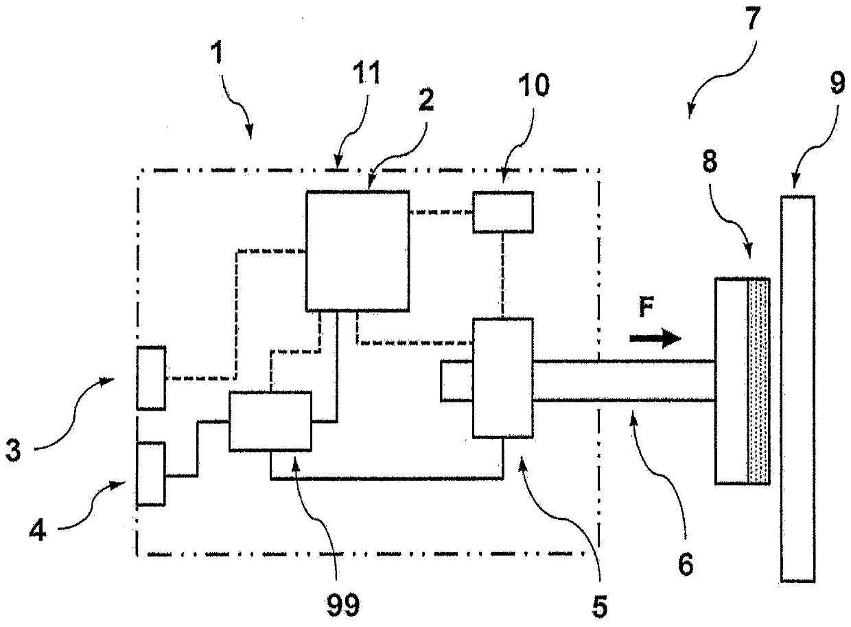
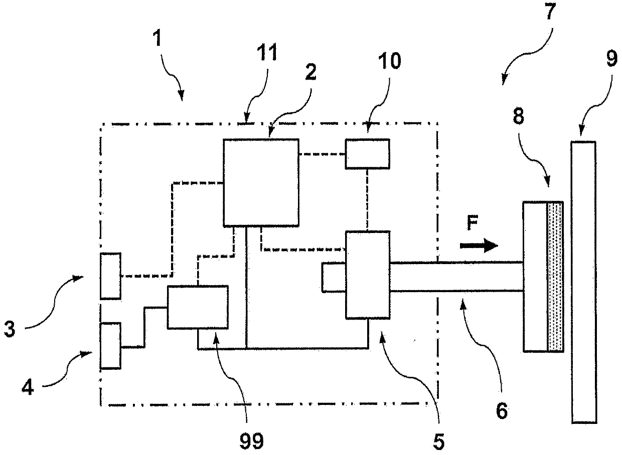
[0020] figure 1 A first embodiment of a brake actuator for a rail vehicle according to the invention is shown. The brake actuator 1 for rail vehicles has: a housing 11; a pressure element 8 configured to be pressed onto a brake disk 9; means 5 for moving the pressure element 8, 6. The device is configured to move the pressing member 8 towards and away from the brake disc 9; the logic unit 2 in the housing 11 is configured to control the pressing member 8 Moving components 5 , 6 ; control interface 3 on housing 11 for connection to a higher-level controller of the rail vehicle located outside the housing; on housing 11 for supplying brake actuator 1 An energy supply interface 4 ; and a pressing force detection unit 10 in the housing 11 for detecting the actual pressing force F of the pressing member 8 on the brake disc 9 . Furthermore, brake actuator 1 has power electronics 99 with an energy store, which is arranged in housing 11 and is assigned to only one brake actuator 1 ....


PUM


Abstract

The invention relates to a brake actuator (1) for a rail vehicle, comprising a housing (11); a pressing part (8) which is configured so as to be pressed onto a brake disc (9); means (5, 6) for movingthe pressing part (8); a logic unit (2) in or on the housing (11), said logic unit being configured to control the means (5, 6) for moving the pressing part (8); a control connection (3) on the housing (11); a supply connection (4) on the housing (11) for supplying the brake actuator (1) with energy; and a power electronics unit (99) with an energy store, said power electronics unit being arrangedin or on the housing (11) and being paired solely with the one brake actuator (1).

Description

technical field [0001] The invention relates to an electromechanical brake actuator according to the preamble of claim 1 . Background technique [0002] DE 10 2009 042 965 A1 discloses an electromechanical brake actuator according to the preamble of claim 1, comprising: a housing; a pressing element configured to be pressed onto a brake disc; for means for moving the pressing member configured to move the pressing member towards and away from the brake disc; a logic unit in the housing configured to control the pressing member for moving the pressing member Moving components; a control interface on the housing for connection to a higher-level controller of the rail vehicle located outside the housing; a supply interface on the housing for supplying energy to the brake actuator; A pressure detection unit in the housing for detecting the actual pressure force of the pressure element on the brake disc. Such electromechanical devices (EM) are in principle considered as an alte...

Claims


Application Information

Patent Timeline
IPC IPC(8): B60T13/66B60T13/74B61H1/00
CPCB60T8/171B61H5/00B61H13/34B60T13/66B60T13/665B60T13/74B60T17/228B60T13/741F16D55/226F16D65/183F16D2066/005B60T8/3255F16D65/18B60T8/1705B60T2270/402B60T2270/414F16D2121/24
Inventor C·莫斯巴赫M-G·埃尔斯托尔普夫C·米勒A·休斯曼
Owner KNORR BREMSE SYST FUR SCHIENENFAHRZEUGE GMBH
Why Eureka
Try Eureka