Scheduling system resource tree generation method, scheduling device and computer storage medium

A scheduling system and resource tree technology, applied in the field of scheduling system resource tree generation method, scheduling device and computer storage medium, can solve the problems of single display method, unable to update the scheduling system in real time, visual display and other problems when the node relationship changes, so as to improve the perception Experience and enrich the effect of application functions

Active Publication Date: 2020-04-24
HARBIN HYTERA TECH CORP
View PDF10 Cites 5 Cited by
  • Summary
  • Abstract
  • Description
  • Claims
  • Application Information

AI Technical Summary

Problems solved by technology

[0004]In the trunking communication system, usually on the visual interface of the scheduling system, there will be a resource tree list displaying the terminal hierarchical structure and organizational structure information, along with the overall business With the continuous development of the resource tree list, there are infinite possibilities for the application expansion of the resource tree list. Especially in the daily command and dispatch work, there will be situations where it is necessary to obtain the corresponding terminal information from the map, and the resources in the existing dispatch system The tree has no way to visually display this data, which requires manual statistics from the map, and in the statistical process, when the amount of data is large, there will be large data deviations, resulting in information loss
[0005]Moreover, most of the resource tree display and update methods of the existing dispatching system use the resource tree displayed by the dispatching console to be consistent with the organization node of the account opened in the network management, and the display method is too Single, only the hierarchical relationship set by the user, the business relationship is poor, and the change of the node relationship on the network management cannot be updated to the dispatching system in real time

Method used


Image

  • Scheduling system resource tree generation method, scheduling device and computer storage medium
  • Scheduling system resource tree generation method, scheduling device and computer storage medium

Examples


Embodiment Construction

[0032] In order to have a clearer understanding of the technical features, purposes and effects of the present invention, the specific implementation manners of the present invention will now be described in detail with reference to the accompanying drawings.

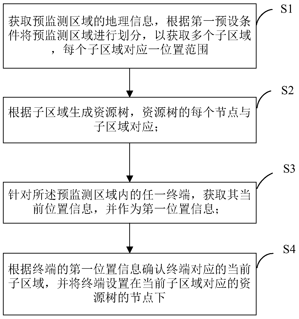
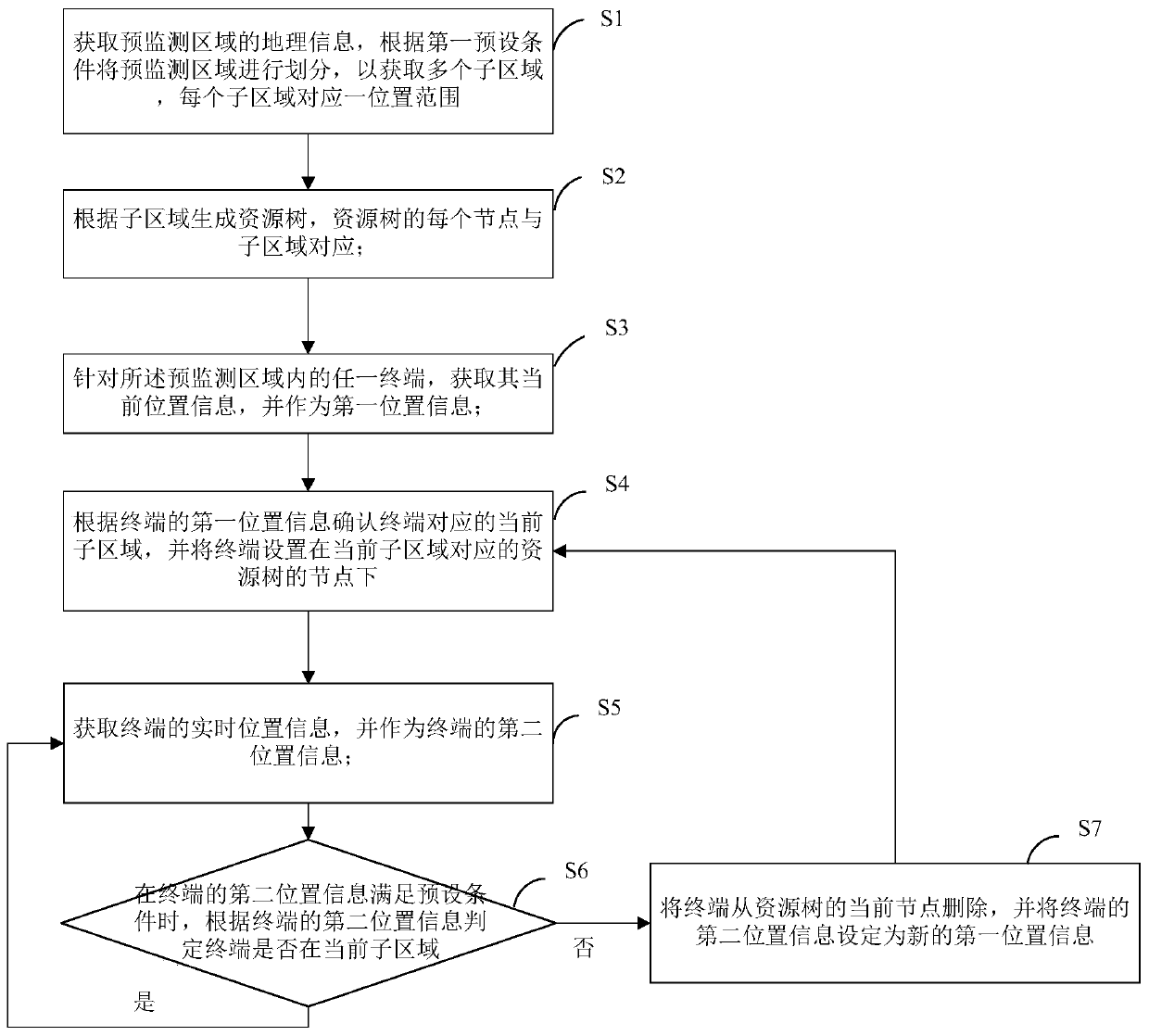
[0033] Such as figure 1 As shown, in the first embodiment of the scheduling system resource tree generating method of the present invention, including:

[0034] S1. Obtain the geographic information of the pre-monitoring area, and divide the pre-monitoring area to obtain multiple sub-areas, each sub-area corresponds to a location range; specifically, the monitoring area will be divided on the map through the preset geographic information into several subregions of different scopes. It is understood here that the map can be displayed or not displayed. The boundaries of the corresponding sub-regions may or may not be displayed on the map. The pre-monitoring area here can be set according to the coverage of a communicat...


PUM


Abstract

The invention relates to a scheduling system resource tree generation method, a scheduling device and a computer storage medium, and the method comprises the steps: S1, obtaining the geographic information of a pre-monitoring region, dividing the pre-monitoring region to obtain a plurality of sub-regions, and enabling each sub-region to correspond to a position range; S2, generating a resource tree according to the sub-regions, wherein each node of the resource tree corresponds to the sub-regions; S3, for any terminal in the pre-monitoring area, obtaining current position information of the terminal, and taking the current position information as first position information; S4, determining the current sub-region corresponding to the terminal according to the first position information of the terminal, and setting the terminal under the node of the resource tree corresponding to the current sub-region. According to the method, the resource tree is generated by using the geographic information of the terminal, and the number of the real-time terminals in the set area can be visually displayed without using a map, so the perception experience of a user is improved, and the applicationfunctions are enriched.

Description

technical field [0001] The present invention relates to the technical field of communications, and more specifically, to a method for generating a scheduling system resource tree, a scheduling device, and a computer storage medium. Background technique [0002] Trunk Communication system (Trunk Communication system for short), also known as trunking wireless communication system, gathers a certain number of professional users with various types of sparse capacity, and uses the wireless channel of the same bus to carry out multi-purpose, High performance dedicated wireless communication. Trunking communication has the characteristics of dynamic signal allocation and multi-user sharing of channel resources, which make full use of limited wireless channel resources, so that members participating in trunking communication can share rich special functions and services. [0003] With the continuous development of long-term evolution (LTE, Long Term Evolution) trunking services, i...

Claims


Application Information

Patent Timeline
Patent Type & Authority Applications(China)
IPC IPC(8): H04W24/02H04W64/00H04W72/12H04W84/08
CPCH04W24/02H04W64/00H04W72/121H04W72/1263H04W84/08
Inventor 程显耕朱慧中
Owner HARBIN HYTERA TECH CORP
Why Eureka
Try Eureka