
Photo frame capable of improving photo framing efficiency and framing effect

A framing and efficient technology, applied in the direction of picture frames, mirrors, household appliances, etc., can solve the problems of troublesome implementation process, operator damage, unstable fixation, etc., to achieve a wide range of use, convenient framing, and better viewing effect. Effect

Inactive Publication Date: 2020-04-28
引思百尔(杭州)科技有限公司
View PDF1 Cites 0 Cited by
  • Summary
  • Abstract
  • Description
  • Claims
  • Application Information

AI Technical Summary

Problems solved by technology

[0003] A traditional photo frame includes a frame, a transparent display sheet and a baffle. The baffle is set on the back of the frame, and the photo is placed between the transparent display sheet and the baffle. When the photo is framed, it is usually set on the frame. The rotating part rotates through the rotating part and then achieves the purpose of locking and fixing the baffle. This method is prone to problems of unreliable fixing during use
[0004] In order to solve the problem of unreliable fixing, some smaller photo frames are equipped with multiple thin elastic clips on the back of the frame to complete the fixation of the baffle. When using, the multiple elastic clips need to be opened one by one to lock the baffle. Take it away, the implementation process of this method is more troublesome, and the elastic clip has a certain degree of sharpness, it is too late to use external tools when breaking the elastic clip, and it is easy to cause damage to the operator when it is broken by hand. When compared with the placed photos When the photo frame is small, the photo is easy to shake when placed in the photo frame, which affects the use

Method used


Image

  • Photo frame capable of improving photo framing efficiency and framing effect
  • Photo frame capable of improving photo framing efficiency and framing effect
  • Photo frame capable of improving photo framing efficiency and framing effect

Examples


Embodiment 1

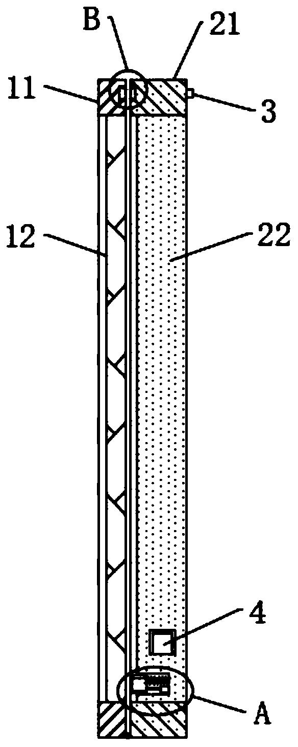
[0045] see figure 1 , a photo frame that can improve the efficiency and effect of framing photos, comprising a front frame body 11 and a rear frame body 21 that are rotatably connected to each other at the bottom, a transparent display sheet 12 is fixed on the inner wall of the front frame body 11, and a fixed display sheet 12 is fixed on the inner wall of the rear frame body 21 A positioning plate 22 is provided, and the right end of the positioning plate 22 is provided with a pendant that can hang the photo frame. When inserting a photo, the photo can move down along the transparent display sheet 12, and finally be located in the gap between the transparent display sheet 12 and the positioning plate 22.

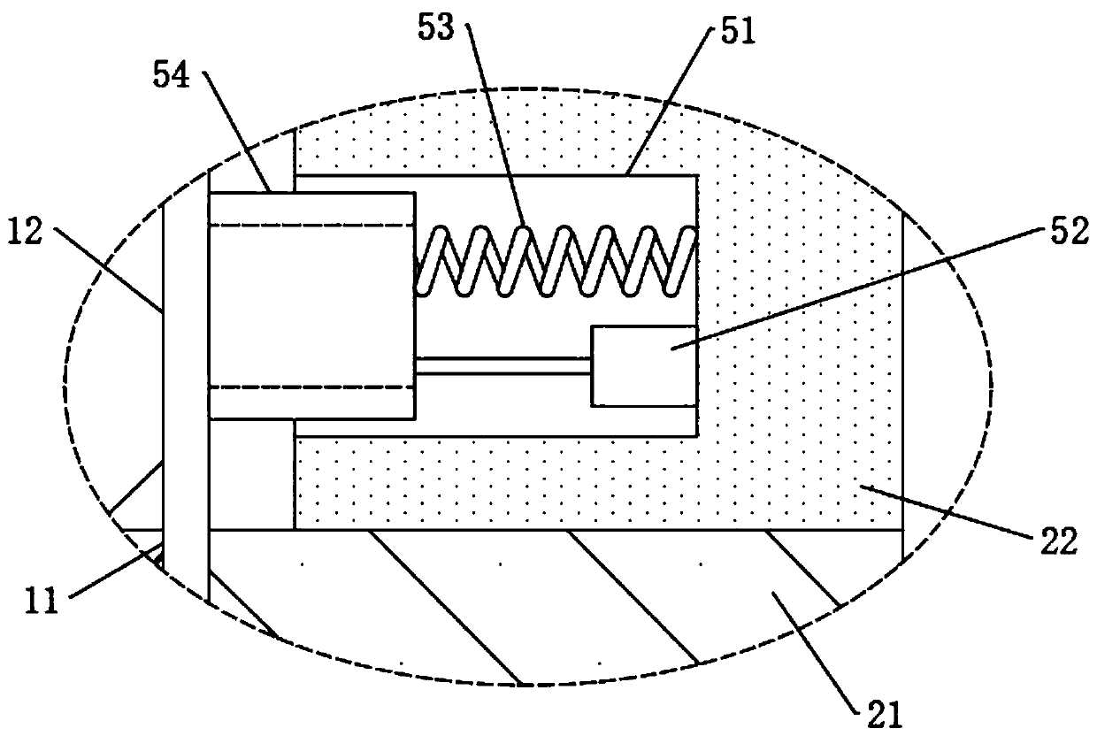
[0046] see figure 2 and Figure 4-6 A group of movable grooves 51 are excavated on the surface of the positioning plate 22 close to the transparent display sheet 12, the distance between the two movable grooves 51 is smaller than the lateral length of the positioning pla...


PUM


Abstract

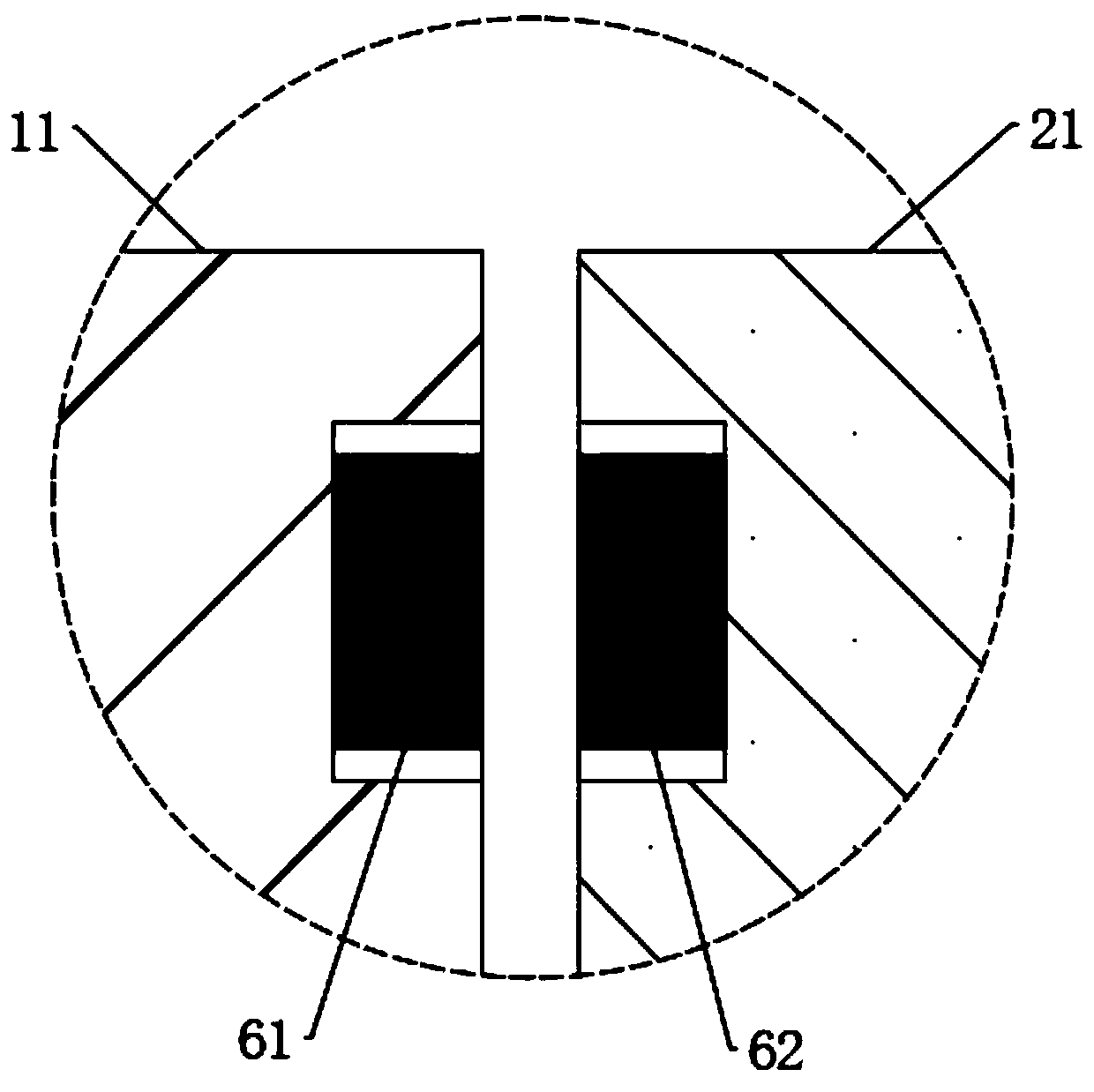
The invention discloses a photo frame capable of improving photo framing efficiency and framing effect and belongs to the field of photo frames. The photo frame comprises a front frame body and a rearframe body, wherein the bottoms of the front frame body and the rear frame body are rotatably connected with each other, a transparent display sheet is fixedly arranged on the inner wall of the frontframe body, a positioning plate is fixedly arranged on the inner wall of the rear frame body, a group of movable grooves are formed in the surface, close to the transparent display sheet, of the positioning plate, a clamping piece is arranged in the movable groove, a cavity is dug in the positioning plate, a photo can be put in through a gap rotationally connected between the front frame body andthe rear frame body, the positions of the photos can be further fixed through the arrangement of the clamping pieces, so that the photo is not easy to shake, and the viewing effect is better. The front frame body and the rear frame body are closed through the arrangement of a closing piece, photo framing is more convenient through the combination mode of the components, operators are not prone tobeing hurt, the use effect is better, the use range is wide, and the photo frame can be suitable for framing of large and small photos.

Description

technical field [0001] The invention relates to the field of photo frames, more specifically, to a photo frame that can improve the efficiency and effect of photo framing. Background technique [0002] Photo frame: (Frame), similar to a square, with a hollow inside, and the blank space is just for frequently used photos. It is mainly used for the positioning of the four sides of the photo and to enhance its aesthetics. It is also beneficial to protect the quality of the photo, like a photo frame with glass, which can prevent the photo from discoloration and yellowing, etc., and is a decorative item. [0003] A traditional photo frame includes a frame, a transparent display sheet and a baffle. The baffle is set on the back of the frame, and the photo is placed between the transparent display sheet and the baffle. When the photo is framed, it is usually set on the frame. The rotating part rotates through the rotating part and then achieves the purpose of clamping and fixing ...

Claims


Application Information

Patent Timeline
Patent Type & Authority Applications(China)
IPC IPC(8): A47G1/14
CPCA47G1/14
Inventor 陈帆帆
Owner 引思百尔(杭州)科技有限公司
Learn More