A Method of Establishing a Current Source Model for Charge Sharing

A technology for charge sharing and establishing methods, applied in electrical digital data processing, CAD numerical modeling, instruments, etc., can solve the problem that the current source injection model cannot solve the problem of charge sharing, and achieve the effect of solving the problem of charge sharing

Active Publication Date: 2021-08-03
UNIV OF ELECTRONICS SCI & TECH OF CHINA
View PDF3 Cites 0 Cited by
  • Summary
  • Abstract
  • Description
  • Claims
  • Application Information

AI Technical Summary

Problems solved by technology

[0008] The purpose of the present invention is to solve the problem that the above-mentioned existing current source injection model cannot solve the charge sharing problem, and proposes a method for establishing a charge sharing-oriented current source model

Method used


Image

  • A Method of Establishing a Current Source Model for Charge Sharing
  • A Method of Establishing a Current Source Model for Charge Sharing
  • A Method of Establishing a Current Source Model for Charge Sharing

Examples


Embodiment Construction

[0025] The present invention will be further described below in conjunction with the accompanying drawings and specific embodiments.

[0026] 1. The diffusion equation of carriers caused by implanted ions is modeled as:

[0027]

[0028] Among them, Q L =10(LET), D. n Indicates the diffusivity of electrons, D p Represents the diffusivity of holes, r is the diffusion distance, and q is the electron charge. You can refer to "Semiconductor Physics".

[0029] Further there are:

[0030]

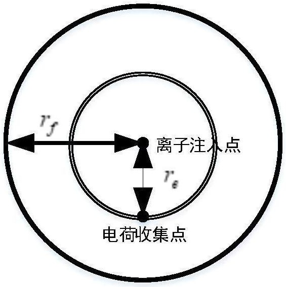
[0031] 2. Introduce injection distance r e , that is, the distance from the injection point to the collection point, then in r e The total current at is modeled as:

[0032]

[0033] Among them, D n,p is the carrier diffusivity, I p (t) for figure 1 The total current on the inner equivalent circle.

[0034] 3. Introduce the reference distance r f , the reference distance is the maximum influence distance of ion implantation. Without loss of generality, suppose a collection ...


PUM


Abstract

The invention discloses a method for establishing a charge sharing-oriented current source model. According to the type of implanted ions, the linear transmission energy of the implanted ions is determined; a reference distance is obtained through simulation modeling, and the reference distance is the maximum influence distance of ion implantation; The depth of charge collection is obtained through simulation modeling; the bipolar amplification factor of charge collection by the device is obtained through simulation modeling; the injection distance to be evaluated is set, and the injection distance is the distance from the injection point to the collection point; according to the obtained injection The linear transmission energy of ions, the reference distance, the depth of charge collection, the bipolar amplification factor of charge collection by the device and the set injection distance can be used to obtain the injection current expression for charge sharing. The method of the present invention is based on the two-dimensional diffusion idea, introduces the injection distance and the reference distance, and solves the problem of charge sharing through the joint action of the injection distance and the reference distance, and the charge caused by a single injected ion can be collected by multiple collection points.

Description

technical field [0001] The invention belongs to the technical field of integrated circuits in electronic science and technology, relates to radiation effect simulation technology and anti-radiation reinforcement technology in avionics, and specifically relates to the evaluation technology of aviation specific integrated circuits. Background technique [0002] Nuclear explosions will produce a large number of high-energy particles, and there are many high-energy particles in space, including heavy particles, protons, alpha particles, neutrons, etc. Once these high-energy particles hit the corresponding semiconductor devices, they may cause single event effects in semiconductor devices, seriously Affect the reliability and life of the electronic system. The single event effect means that the high-energy charged particles in the radiation will undergo energy deposition when passing through the sensitive area of ​​the electronic device, thereby generating a large number of elect...

Claims


Application Information

Patent Timeline
Patent Type & Authority Patents(China)
IPC IPC(8): G06F30/367G06F111/10
Inventor 李磊周婉婷
Owner UNIV OF ELECTRONICS SCI & TECH OF CHINA
Why Eureka
Try Eureka